Eureka AIR delivers breakthrough ideas for toughest innovation challenges, trusted by R&D personnel around the world.

Light emitting device and projector

Inactive Publication Date: 2012-09-20
SEIKO EPSON CORP
View PDF4 Cites 11 Cited by
  • Summary
  • Abstract
  • Description
  • Claims
  • Application Information

AI Technical Summary

Benefits of technology

[0008]An advantage of some aspects of the invention is to provide a light emitting device that may be applied to a projector in which distances between plural light output parts may be made larger and a light emitting device is provided immediately below a light valve. Further, an advantage of some aspects of the invention is to provide a projector having the light emitting device.

Problems solved by technology

In the technology described in Patent Document 1, it is difficult to arrange plural light output parts at distances according to various lens arrays with different intervals, and the technology is not applicable to the projector of the above described type.

Method used


Image

  • Light emitting device and projector
  • Light emitting device and projector
  • Light emitting device and projector

Examples


Embodiment Construction

[0059]Below, a preferred embodiment of the invention will be explained with reference to the drawings.

1. Light Emitting Device

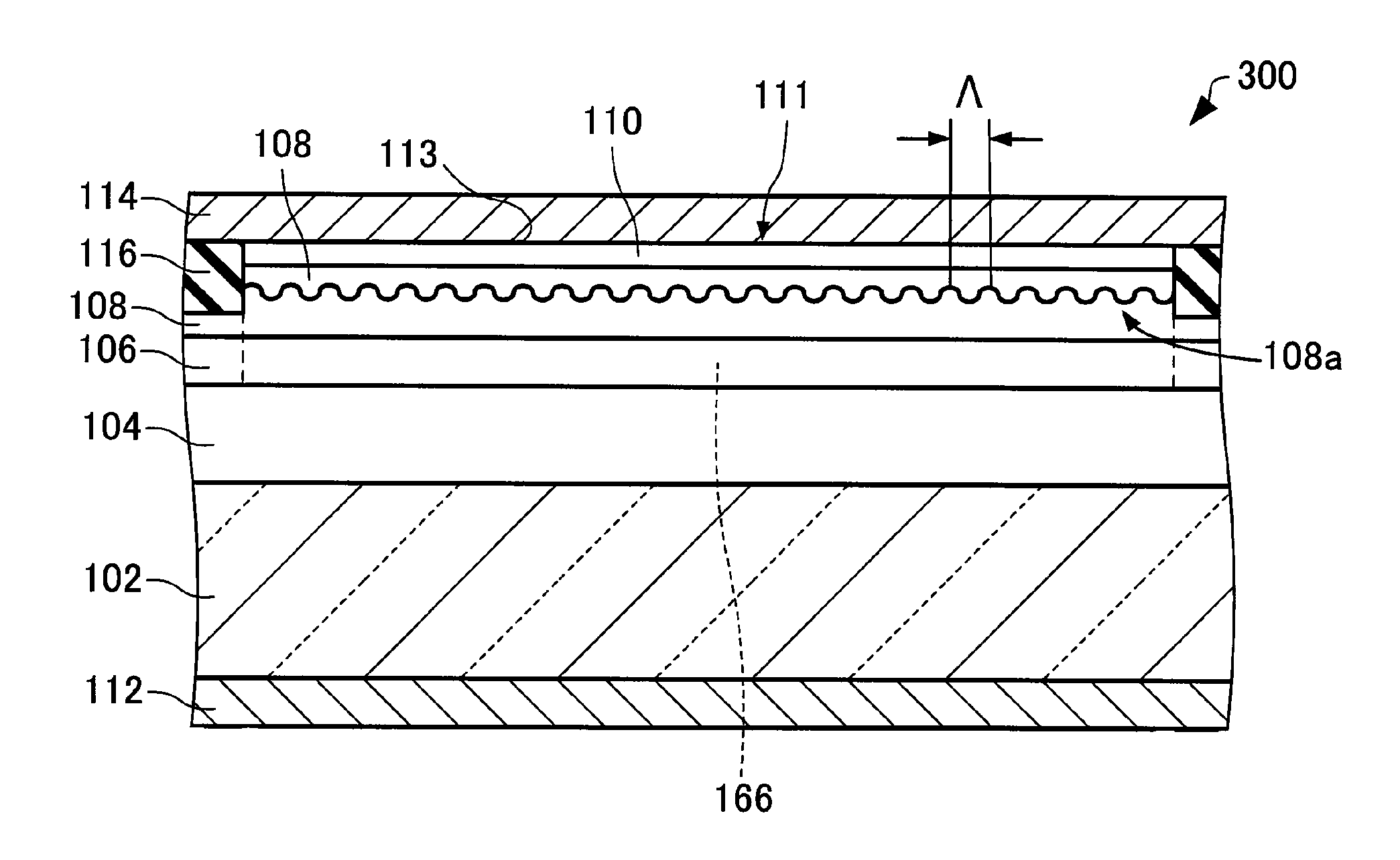
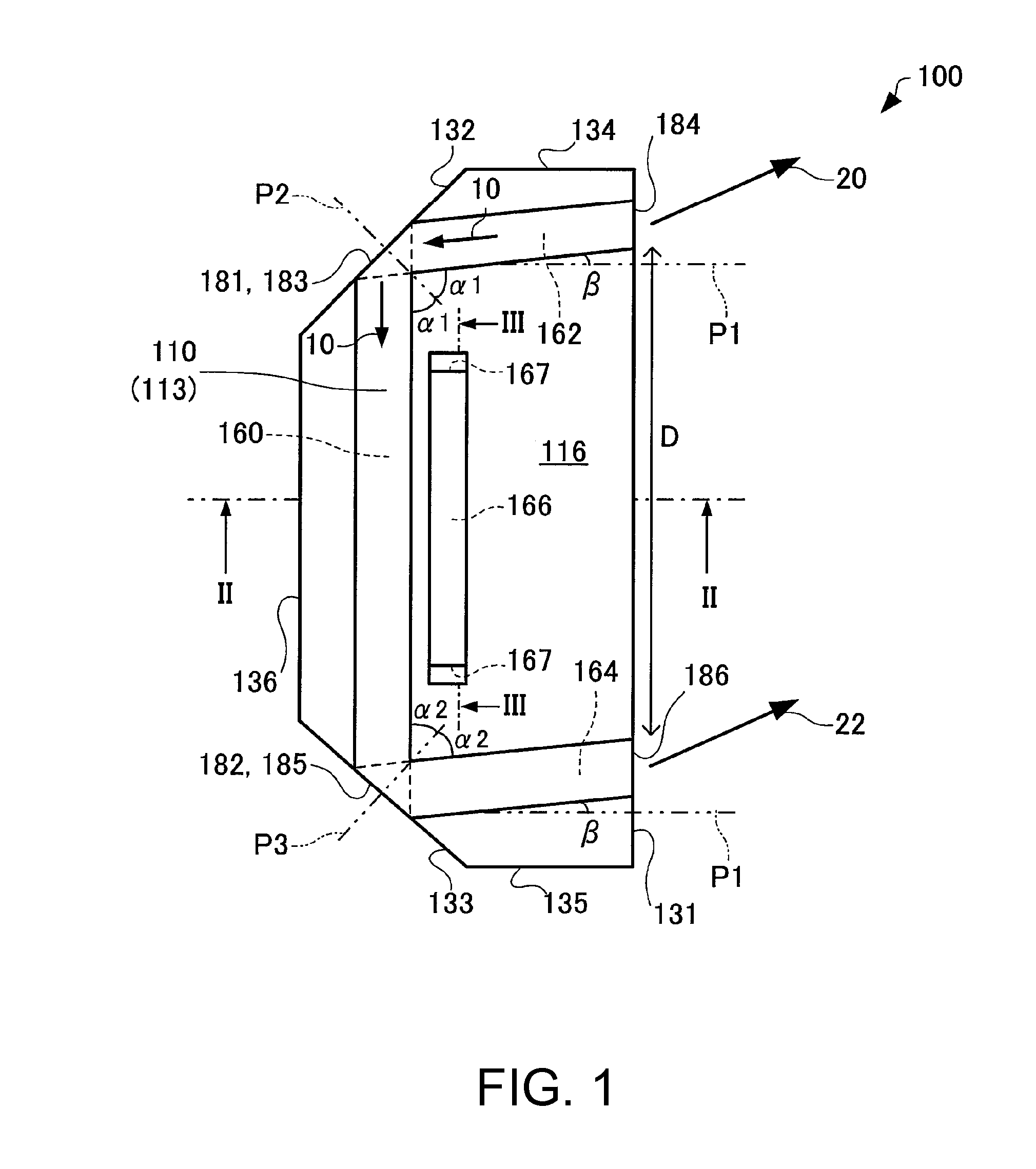
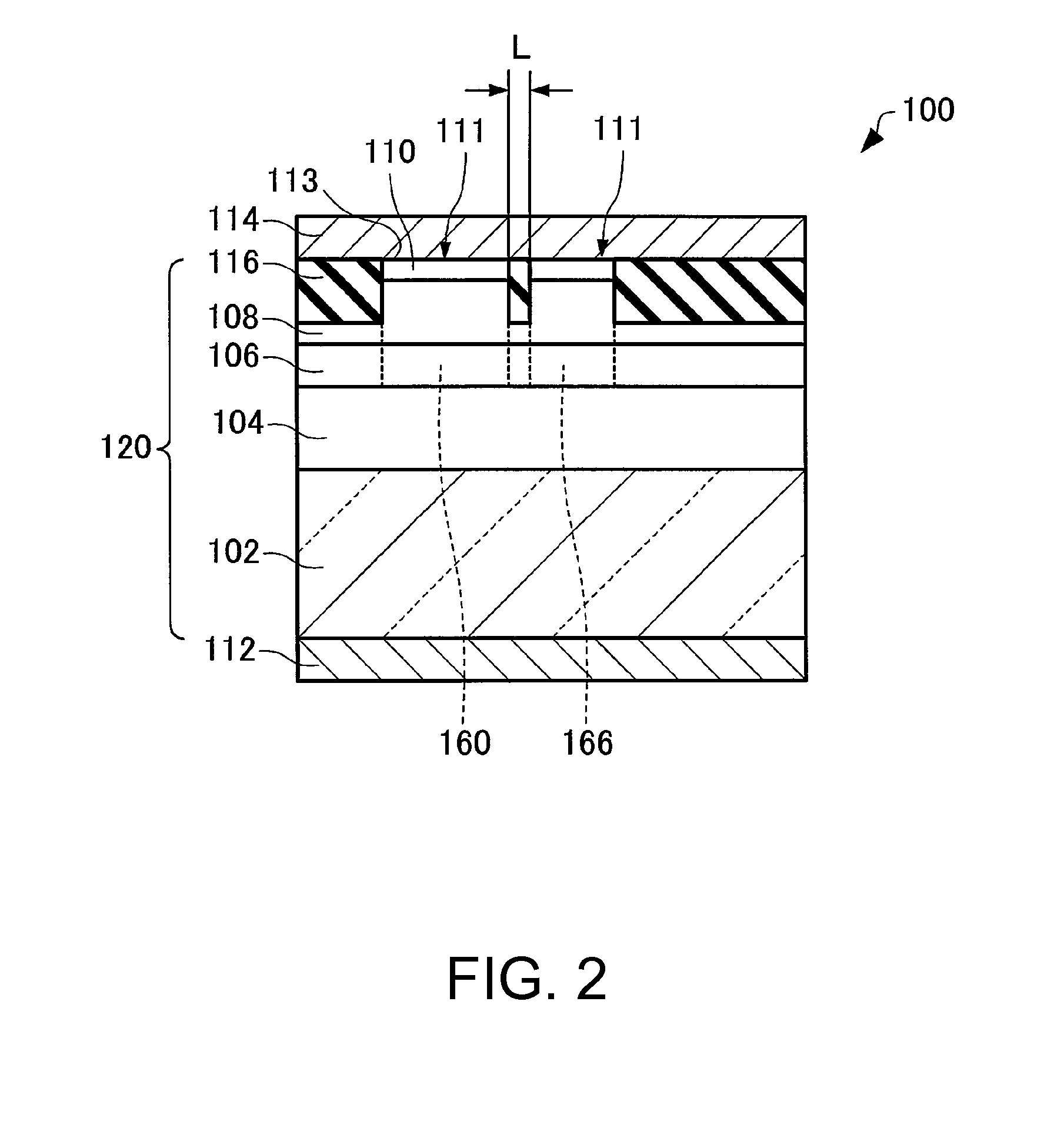
[0060]First, a light emitting device according to the embodiment will be explained with reference to the drawings. FIG. 1 is a plan view schematically showing a light emitting device 100 according to the embodiment. FIG. 2 is a sectional view along II-II line of FIG. 1 schematically showing the light emitting device 100 according to the embodiment. FIG. 3 is a sectional view along line of FIG. 1 schematically showing the light emitting device 100 according to the embodiment. Note that, in FIG. 1, for convenience, an illustration of a second electrode 114 is omitted.

[0061]As below, the case where the light emitting device 100 is a light source of an InGaAlP system (red) will be explained.

[0062]As shown in FIGS. 1 to 3, the light emitting device 100 may include a multilayered structure 120, a first electrode 112, and the second electrode 114.

[0063]The multilaye...


PUM


Abstract

A light emitting device includes a first layer that generates light by injection current and forms a waveguide for the light, and an electrode that injects the current into the first layer, wherein the waveguide of the light has a first region, a second region, a third region, and a fourth region, the first region and the second region are connected at a first reflection part, the first region and the third region are connected at a second reflection part, the second region and the third region are tilted at the same angle and connected to an output surface, a distance between the fourth region and at least one of the first region, the second region, and the third region is a distance that produces evanescent coupling, and the fourth region forms a resonator.

Description

BACKGROUND[0001]1. Technical Field[0002]The present invention relates to a light emitting device and a projector.[0003]2. Related Art[0004]A super luminescent diode (hereinafter, also referred to as “SLD”) is a semiconductor light emitting device that can output several hundreds of milliwatts similar to a semiconductor laser, while exhibiting a broadband spectrum and thus being incoherent similar to a typical light emitting diode.[0005]An SLD is sometimes used as a light source of a projector. To realize a small and high-brightness projector, it is necessary to use a light source having high light output and small etendue. For the purpose, it is desirable that light output from plural gain regions travel in the same direction. In Patent Document 1 (JP-A-2010-3833), by combining a gain region having a linear shape and a gain region having a flexed shape via a reflection surface, light output from light output parts (light emitting areas) of the two gain regions travel in the same dir...

Claims


Application Information

Patent Timeline
IPC IPC(8): H01L33/60
CPCH01L33/0045G03B21/2033H01L33/465
Inventor MOCHIZUKI, MASAMITSU
Owner SEIKO EPSON CORP
Why Eureka
Eureka Blog
Learn More