High Voltage Rectifier and Switching Circuits

a switching circuit and high voltage technology, applied in the field of high voltage circuits, can solve the problems of affecting the gate of the depletion-mode transistor, the inability to form as an the inability to achieve the effect of iii-nitride enhancement-mode hemt device,

Active Publication Date: 2012-09-20
INFINEON TECH AMERICAS CORP
View PDF3 Cites 31 Cited by
  • Summary
  • Abstract
  • Description
  • Claims
  • Application Information

AI Technical Summary

Problems solved by technology

The depletion-mode transistor can be, for example, a high electron mobility transistor (HEMT), such as a III-Nitride HEMT, which can support high current and high blocking capability, but it may not be desirable to form as an III-Nitride enhancement-mode HEMT device.
The switching circuit can easily become unstable because the depletion-mode transistor can only support a very small leakage current when it is OFF.
As the gate-source voltage approaches or surpasses the pinch off voltage, the electric filed applied to the gate of the depletion-mode transistor can become too large, thereby rupturing the gate of the depletion-mode transistor or otherwise damaging the switching circuit.
Thus, the design of the switching circuit can be complicated as the diode may leak substantial current when at a high temperature, and in some designs may be a diode that easily leaks current, such as a Schottky diode.
Such rectifier circuit suffers from similar disadvantages discussed above, and the design of this conventional rectifier circuit is also complicated since the diode may leak substantial current, and in some designs may be a diode that easily leaks current, such as a Schottky diode.
The conventional rectifier circuit is thus susceptible to damage by the same mechanism discussed above.

Method used


Image

  • High Voltage Rectifier and Switching Circuits
  • High Voltage Rectifier and Switching Circuits
  • High Voltage Rectifier and Switching Circuits

Examples


Embodiment Construction

[0016]The present invention is directed to improved high voltage rectifier and switching circuits. The following description contains specific information pertaining to the implementation of the present invention. One skilled in the art will recognize that the present invention may be implemented in a manner different from that specifically discussed in the present application. Moreover, some of the specific details of the invention are not discussed in order not to obscure the invention.

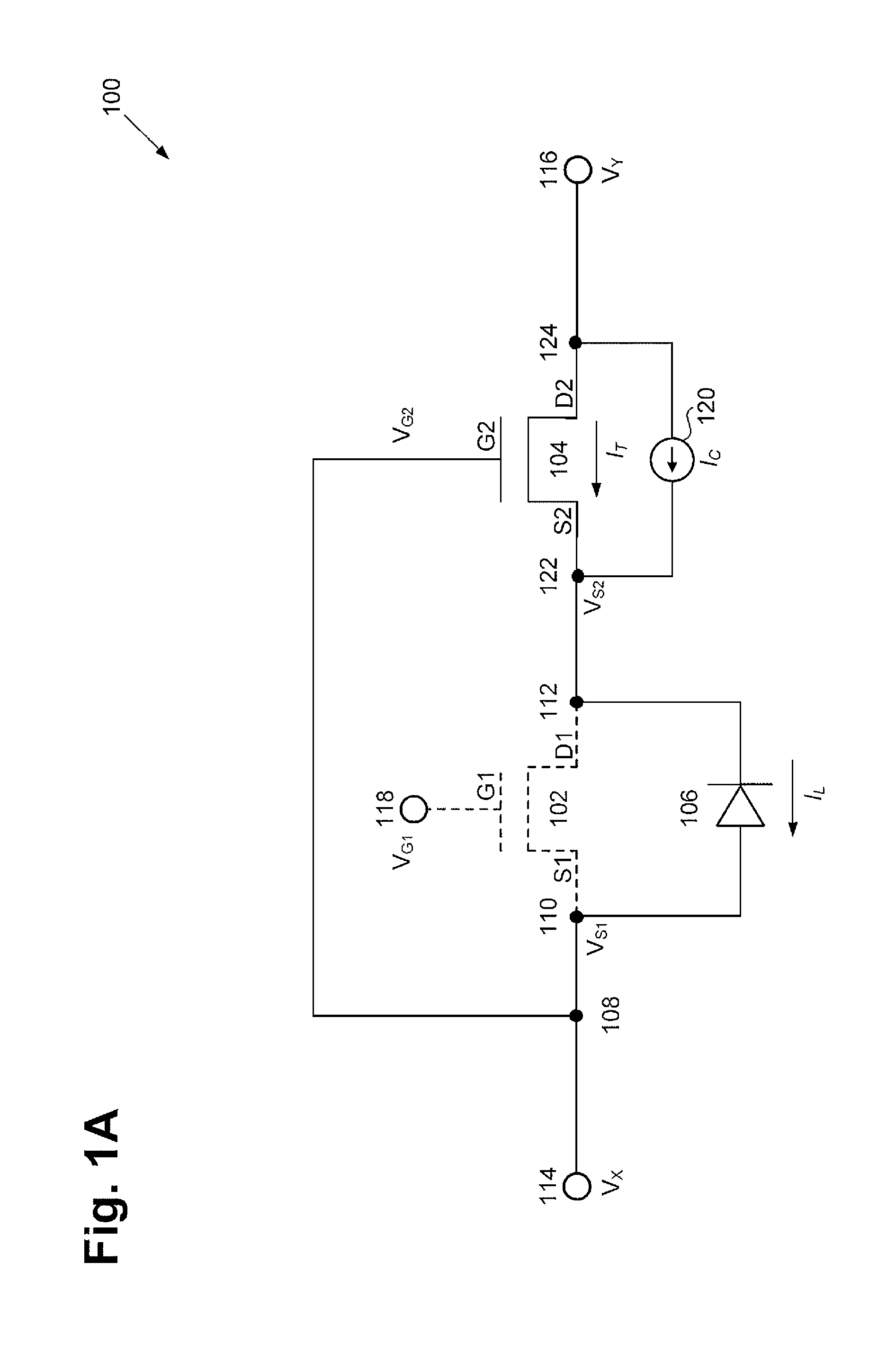
[0017]The drawings in the present application and their accompanying detailed description are directed to merely exemplary embodiments of the invention. To maintain brevity, other embodiments of the present invention are not specifically described in the present application and are not specifically illustrated by the present drawings. FIG. 1A illustrates a circuit diagram of exemplary rectifier / switching circuit 100 (or referred to simply as a “switching circuit” or a “rectifier circuit”) in accorda...


PUM


Abstract

According to one exemplary embodiment, a rectifier circuit includes a diode. A first depletion-mode transistor is connected to a cathode of the diode. Also, at least one second depletion-mode transistor is in parallel with the first depletion-mode transistor and is configured to supply a pre-determined current range to a cathode of the diode. A pinch off voltage of the at least one second depletion-mode transistor can be more negative than a pinch off voltage of the first depletion-mode transistor and the at least one second depletion-mode transistor can be configured to supply the pre-determined current range while the first depletion-mode transistor is OFF. Also, the pre-determined current range can be greater than a leakage current of the first depletion-mode transistor.

Description

[0001]The present application claims the benefit of and priority to a pending provisional application entitled “Improved High Voltage Rectifier and Switching Circuits,” Ser. No. 61 / 454,081 filed on Mar. 18, 2011. The disclosure in that pending provisional application is hereby incorporated fully by reference into the present application.BACKGROUND OF THE INVENTION[0002]1. Field of the Invention[0003]The present invention is generally in the field of high voltage circuits. More particularly, the invention is in the field of high voltage rectifier and switching circuits.[0004]2. Background Art[0005]A depletion-mode transistor can be connected in cascode with an enhancement-mode transistor to form an enhancement-mode switching circuit. The enhancement-mode switching circuit can have a high voltage, such as 600 volts, connected to a drain of the depletion-mode transistor and a low voltage, such as −10 volts, present at the gate of the depletion-mode transistor and at the source of the e...

Claims


Application Information

Patent Timeline
Patent Type & Authority Applications(United States)
IPC IPC(8): H01L29/778H01L27/088
CPCH01L27/0605H01L27/0629H02M7/106H01L29/42364H01L29/7786H01L29/2003
Inventor BRIERE, MICHAEL A.THAPAR, NARESH
Owner INFINEON TECH AMERICAS CORP
Why Eureka
Try Eureka