Optical sensor and electronic apparatus

Active Publication Date: 2012-09-20
SEIKO EPSON CORP
View PDF1 Cites 10 Cited by
  • Summary
  • Abstract
  • Description
  • Claims
  • Application Information

AI Technical Summary

Benefits of technology

[0008]An advantage of some aspects of the invention is that it provides an optical sensor, an electronic apparatus, and the

Problems solved by technology

However, in a case where a gap area is generated on the side wall of the angle limiting filter, there is a problem in that incidence light leaks from the gap area so as to degrade the angle controllability.
In such a case, there is a problem in that the number of

Method used


Image

  • Optical sensor and electronic apparatus
  • Optical sensor and electronic apparatus
  • Optical sensor and electronic apparatus

Examples


Embodiment Construction

[0050]Hereinafter, preferred embodiments of the invention will be described in detail. However, the embodiments described below are not for the purpose of limiting the scope of the invention described in the appended claims, and it cannot be determined that all the configurations described in the embodiments are essential as solving means according to the embodiments of the invention. In addition, although an example will be described below in which the optical sensor is a spectroscopic sensor, the optical sensor according to the embodiments is not limited to a spectroscopic sensor as will be described later.

1. Configuration

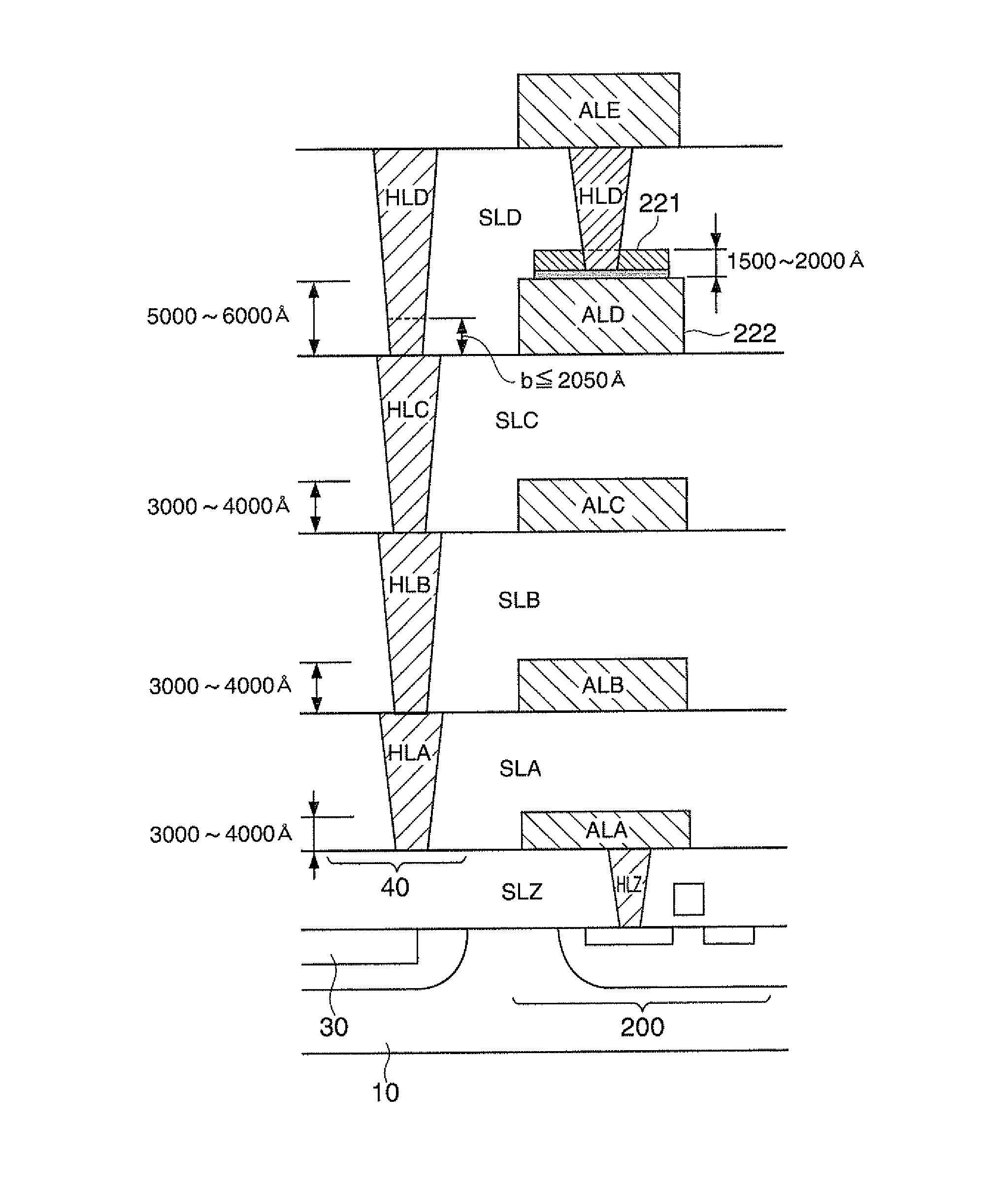
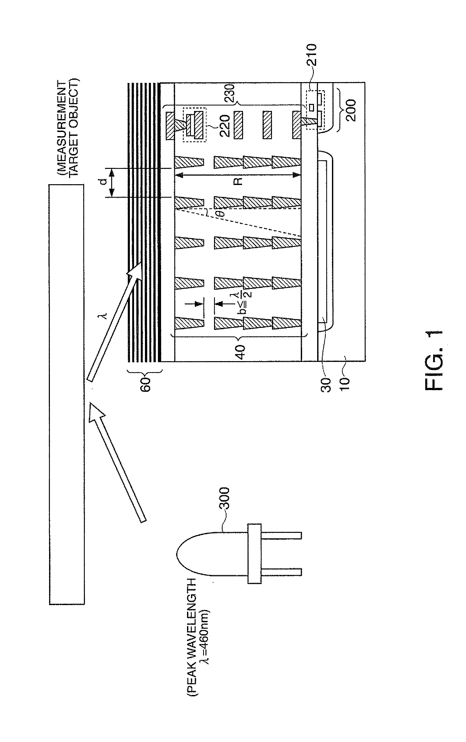
[0051]FIG. 1 shows a configuration example of a spectroscopic sensor according to this embodiment. Hereinafter, for the simplification, the configuration of this embodiment will be schematically shown, and the dimensions and the ratios illustrated in the figures are not real values.

[0052]FIG. 1 shows a cross-sectional view of a spectroscopic sensor taken along a ...


PUM


Abstract

An optical sensor includes an impurity region for a photodiode and an angle limiting filter limiting the incidence angle of incidence light incident to a light receiving area of the photodiode, which are formed on a semiconductor substrate. The angle limiting filter is formed by at least a first plug corresponding to a first insulating layer and a second plug corresponding to a second insulating layer located in an upper layer of the first insulating layer. Between the first plug and the second plug, there is a gap area having a gap space that is equal to or less than λ/2.

Description

[0001]The entire disclosure of Japanese Patent Application No. 2011-058182, filed Mar. 16, 2011 is expressly incorporated by reference herein.BACKGROUND[0002]1. Technical Field[0003]The present invention relates to an optical sensor, an electronic apparatus, and the like.[0004]2. Related Art[0005]Recently, measurement using an optical sensor has been applied to various fields. For example, in order to diagnose or test target objects, spectral sensors are used. As such spectral sensors, there are pulse oximeters that measure the oxygen saturation in blood by using the light absorption of hemoglobin and saccharimeters that measure the sugar content of a fruit by using light absorption of sugar. In addition, illuminance sensors that are used for measuring the illuminance and the like are used.[0006]JP-A-6-129908 and JP-A-2006-351800 are examples of the related art.[0007]Among such optical sensors, there are optical sensors that limit the incident angle of incidence light by using an an...

Claims


Application Information

Patent Timeline
IPC IPC(8): H01L31/02
CPCH01L31/02327H01L31/103
Inventor UEMATSU, AKIRATERASHIMA, YOSHIYUKISATO, YOICHIMATSUO, ATSUSHI
Owner SEIKO EPSON CORP
Why Eureka
Try Eureka