
Configurable, repairable, and recyclable cargo pallet

a cargo pallet and repairable technology, applied in the field of configurable, repairable, recyclable, adjustable load capacity cargo pallets, can solve the problems of not being able to disclose the design of repairable, recyclable, and reusable cargo pallets, and achieve the effects of preventing deforestation, long useful life of pallets, and positive impact on the environmen

Inactive Publication Date: 2012-09-27
HIDALGO EDGAR
View PDF17 Cites 12 Cited by
  • Summary
  • Abstract
  • Description
  • Claims
  • Application Information

AI Technical Summary

Benefits of technology

[0021]This invention is a new cargo pallet that is repairable, reusable, recyclable, lightweight, robust, and configurable to different load capacities to transport and store a great variety of loads. This invention consists of an industrializable pallet and its manufacturing and assembling process to substitute traditional wooden pallets; consequently, a positive impact on the environment is achieved by preventing deforestation. The pallet of this invention is a versatile, low-cost, long useful life, robust, and non-slip pallet, to be not only acceptable to replace wooden pallets but also to improve them while performing the same or similar functions. While the wooden pallets are disposable, the plastic pallets of this invention are to be continuously reusable, and if an entire pallet or some of its parts are damaged, they can be repaired, and the damaged parts can be recycled. Other advantages of the plastic pallets in this invention, with respect to wooden pallets, are that they do not produce splinters and they do not need thermal or chemical treatments. The new pallet is built with strong and lasting components to obtain a long useful life of the pallet; the connection of the components in made in such a way to avoid deformations of the pallet when the pallet is subjected to impacts or under normal use.
[0023]The thickness of the flange and web of the central beams, thickness of the walls of the platform members, and thickness of the reinforcing ribs along the beams and the platform members can be adjusted in the manufacturing process to make the beams or platform members more or less robust. To prevent sliding of the cargo on the pallet and of the pallet on the ground, shelves, or forklift, non-slip rubber blocks are inserted in several places along the platform members. The I-shaped beams of the pallet have a row of conical protuberances, or conical pins, centered along their flat top and bottom surfaces, and they are used to create interference and engagement action with the platform members when such conical protuberances are inserted in the corresponding conical holes on the flat surfaces of the platform members to avoid relative displacement or rotation between the beams and the platform members and to contribute carrying shear stresses between the platform members and the beams. These conical protuberances are also used to keep the main components of the pallet together in a stable manner even when small dimensional changes occur due to possible variations in temperature, loads, or stress relaxation. The beams are assembled parallel to each other by connecting platform member perpendicular to the beams to form the top and bottom non-slip platforms of the pallet to transport or store cargo. The beams are separated to leave empty spaces that are used to manipulate the pallet by allowing inserting the forks of forklifts or similar material handling equipment. Between each pair of said conical protuberances of the beams, there is a hole that coincides with another hole in the platform members when they are aligned to be coupled; such holes might be threaded or not and are used to insert bolts that strongly connect and fasten the platform members and the beams to form the pallet. Therefore, the platform members and beams of the new pallet are characterized by having holes that coincide and are evenly spaced to attach them with bolts, washers, and nuts. The flat sides of the platform members have corresponding conical holes to insert said conical protuberances of the beams, and between each pair of these conical holes, there are holes of larger diameter to insert the bolts and accommodate the washers and nuts used to connect the beams and the platform members.
[0024]This invention is a new adjustable load capacity pallet constructed by interconnecting and interlocking beams and platform members made through the plastic injection molding method. The adjustable load capacity of the pallet can be achieved in numerous ways, by varying the thicknesses of the walls and / or the reinforcing ribs of the beams and / or platform members and by varying the number of beams and / or the number of platform members at the top and / or bottom of the pallet. The platform members have U-shaped cross section and flat ends and they have a grid of interconnected reinforcing ribs that runs perpendicular, longitudinal, and diagonally along the members from one end to the other. The central beams of the pallet are constructed with U-shaped cross section, flat ends, and with a grid of interconnected reinforcing ribs that runs at each side of the web of the beam in a perpendicular, longitudinal, and diagonal way along the length of the beams. Centered along the beams, and on the top and bottom surfaces, there are rows of conical protuberances required to be inserted into corresponding conical holes in the flat surfaces of the platform members to speed up the pallet assembling process and to facilitate alignment and engagement between the beams and the platform members, and to maintain a stable and robust connection that prevents slippage or relative rotation between the central beams and the platform members.

Problems solved by technology

Even though several pallets have been designed in the past, the applicant believes that none of them discloses a design of a repairable, recyclable, and reusable cargo pallet with a modular structure, configurable load capacity, and with non-slip rubber surfaces to prevent sliding of the cargo on the pallet and of the pallet on the ground, shelf, and forklift.

Method used


Image

  • Configurable, repairable, and recyclable cargo pallet
  • Configurable, repairable, and recyclable cargo pallet
  • Configurable, repairable, and recyclable cargo pallet

Examples


Embodiment Construction

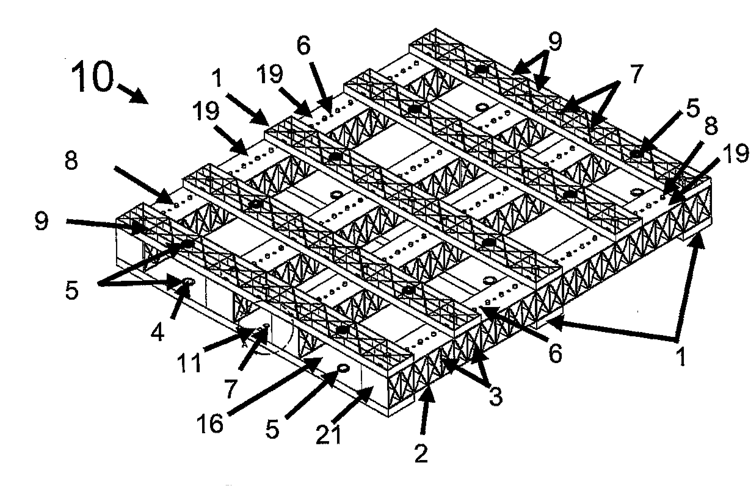
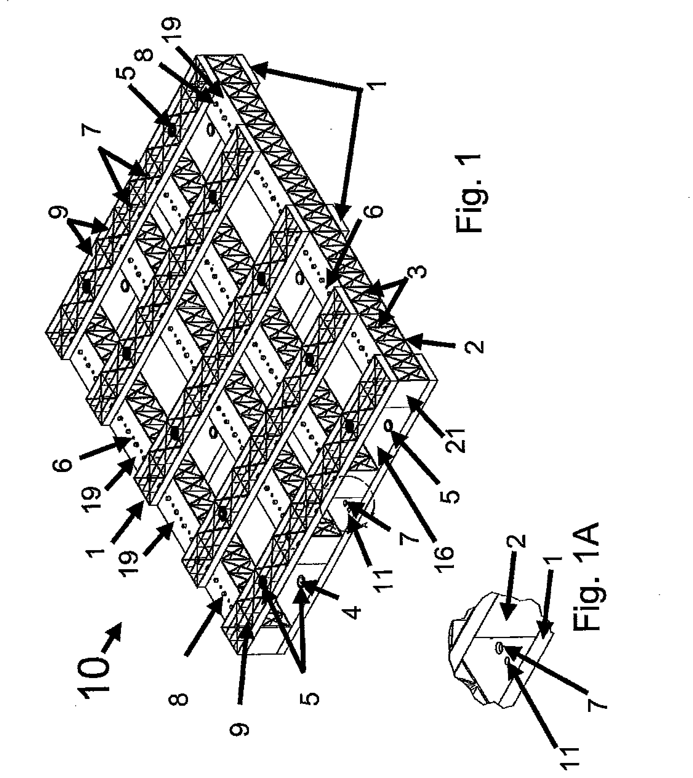
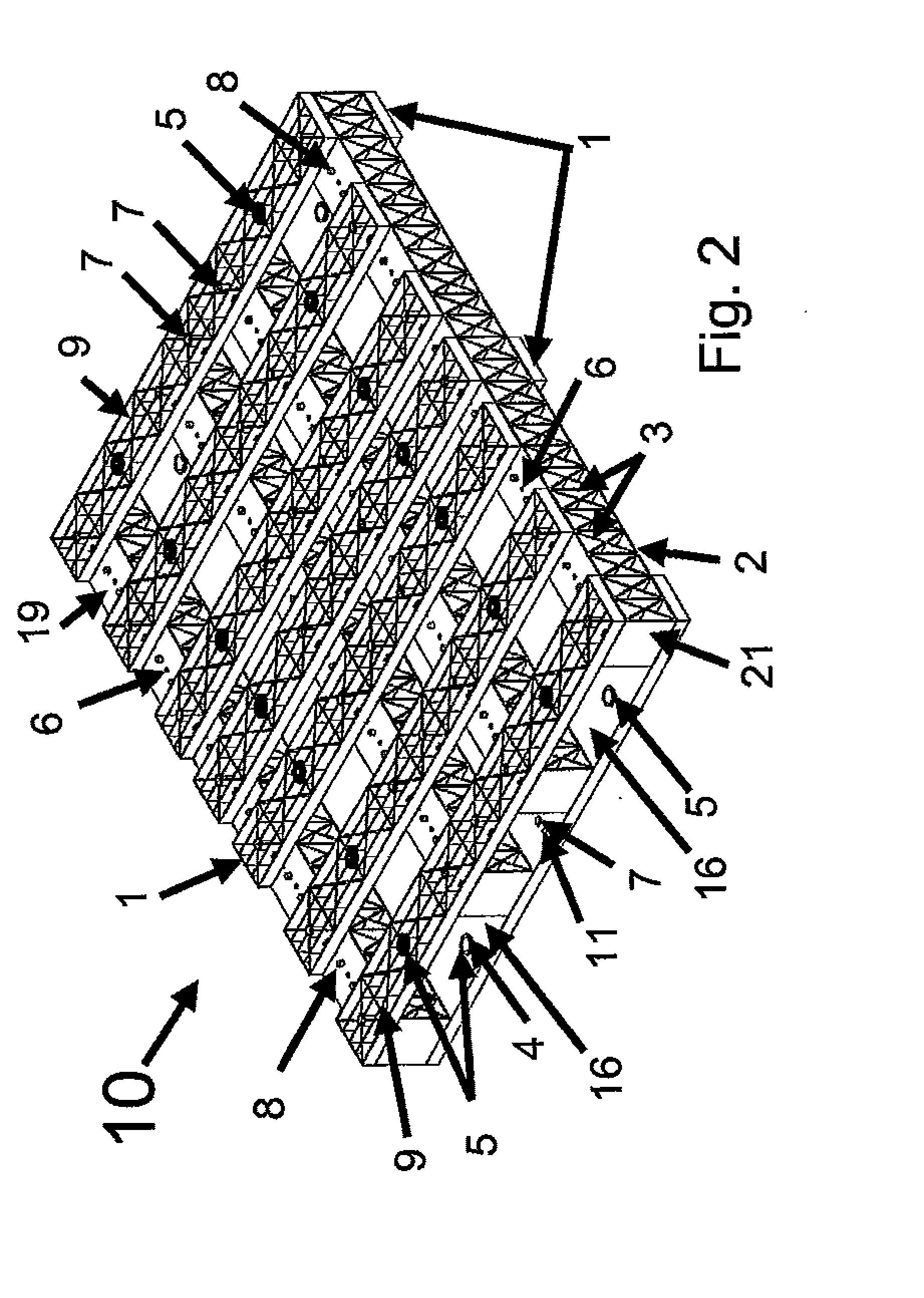
[0041]Considering the characteristics of this invention as explained above, the new pallet 10 is described in more detail next when read in conjunction with the accompanying drawings, in which:

[0042]Referring to FIGS. 1 and 2, this invention is identified as pallet 10 that is configurable for different applications and load capacities depending on the number and the thickness of the walls of the central beams 2 and platform members 1 and also depending on the thickness of the reinforcing ribs 3 and 9. Several central beams 2 are placed parallel to each other and connected with platform members 1 at the top and at the bottom sides of the beams 2. As shown in FIGS. 1 and 2, the number of platform members 1 at the top of beams 2 could be the same as or different to the number of members 1 at the bottom of beams 2. The pallet model is specified by three numbers indicating the number of platform members 1 at the top, the number of central beams 2, and the number of platform members 1 at ...


PUM


Abstract

The present invention relates to a lightweight and versatile pallet and its manufacturing and assembling method. It consists of the design of a repairable, recyclable, and reusable pallet with a modular structure, configurable load capacity, and with non-slip rubber surfaces to prevent sliding of the cargo on the pallet and of the pallet on the ground, shelf, and forklift or other pallet handling equipment. This pallet is to be used in numerous commercial and industrial applications. An embodiment of the platform members used to form the bottom and top surfaces of the pallet can be used to construct other flat platforms such as walls, floors, and molds for pouring concrete structures.

Description

OTHER RELATED APPLICATIONS[0001]The present application is related to pending PCT application No. PCT / CR09 / 000,001, filed on Dec. 18, 2009, belonging to the same applicant, Edgar Hidalgo Vargas.BACKGROUND OF THE INVENTION[0002]1. Field of the Invention[0003]The present invention relates to a configurable, repairable, recyclable, and adjustable load capacity cargo pallet and to its manufacturing and assembling method.[0004]2. Description of the Related Art[0005]The applicant considers that the closest references correspond to the references discussed below. However, they differ from the present invention in that none of them disclose a simple design of a repairable, recyclable, and reusable cargo pallet with the following characteristics:[0006]a) A modular structure with configurable load capacity by varying the robustness and / or the number of the components that make up the new pallet.[0007]b) Non-slip rubber surfaces are used to prevent sliding of the cargo on the pallet and of the...

Claims


Application Information

Patent Timeline
Patent Type & Authority Applications(United States)
IPC IPC(8): B65D19/38B65D19/26
CPCB65D19/0095B65D2519/0084B65D2519/00069B65D2519/00104B65D2519/00273B65D2519/00293B65D2519/00298B65D2519/00323B65D2519/00333B65D2519/00353B65D2519/00373B65D2519/00407B65D2519/00412B65D2519/00417B65D2519/00572B65D2519/00034Y02W30/80
Inventor HIDALGO, EDGAR
Owner HIDALGO EDGAR
Learn More