
Method of producing color change in a substrate

a substrate and color technology, applied in the field of activation colorants, can solve the problems of inability to easily adapt the order in which manufacturers have chosen to provide for colored regions, and equipment can represent a significant capital cost to manufacturing,

Active Publication Date: 2012-09-27
THE PROCTER & GAMBLE COMPANY
View PDF2 Cites 36 Cited by
  • Summary
  • Abstract
  • Description
  • Claims
  • Application Information

AI Technical Summary

Benefits of technology

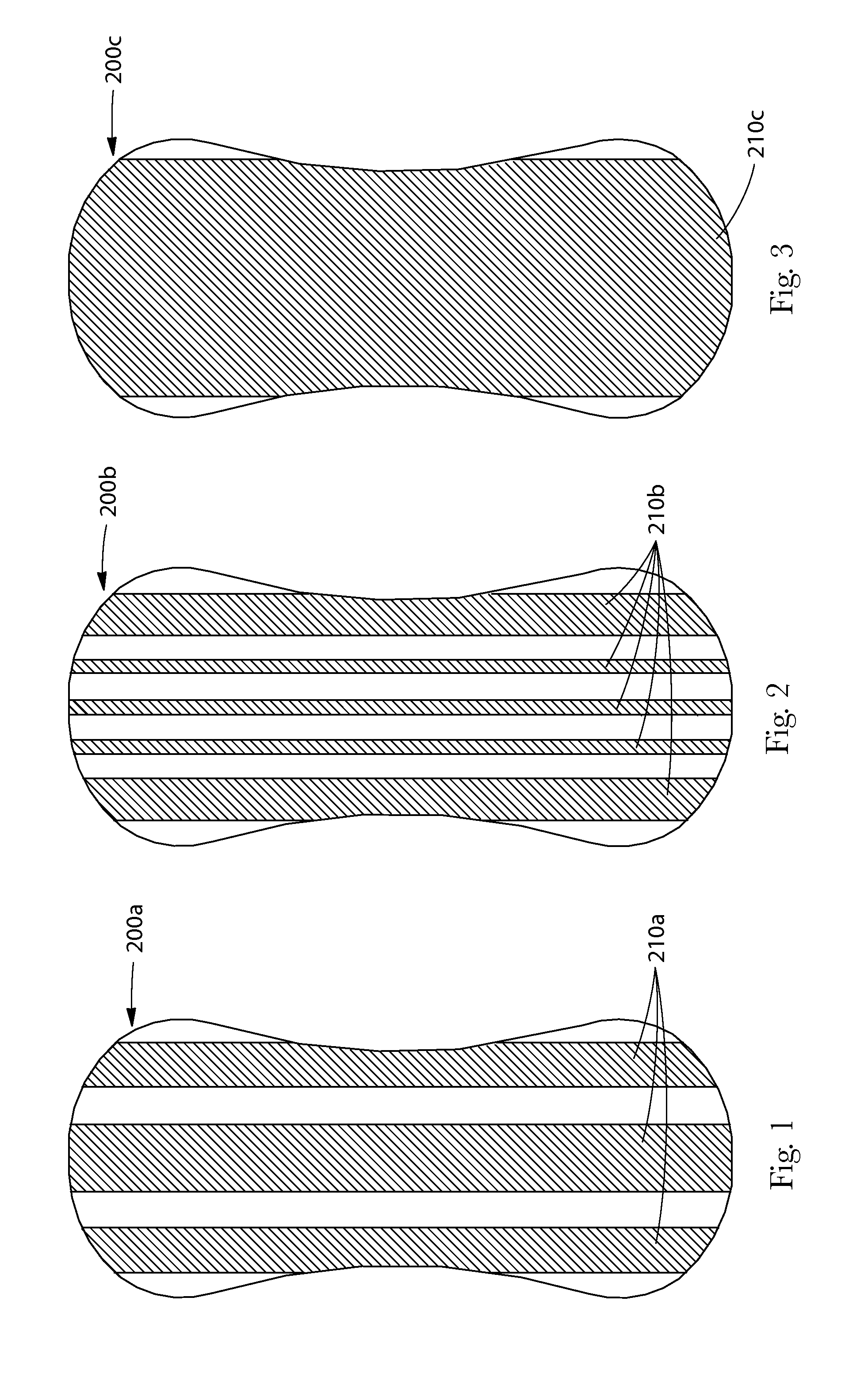
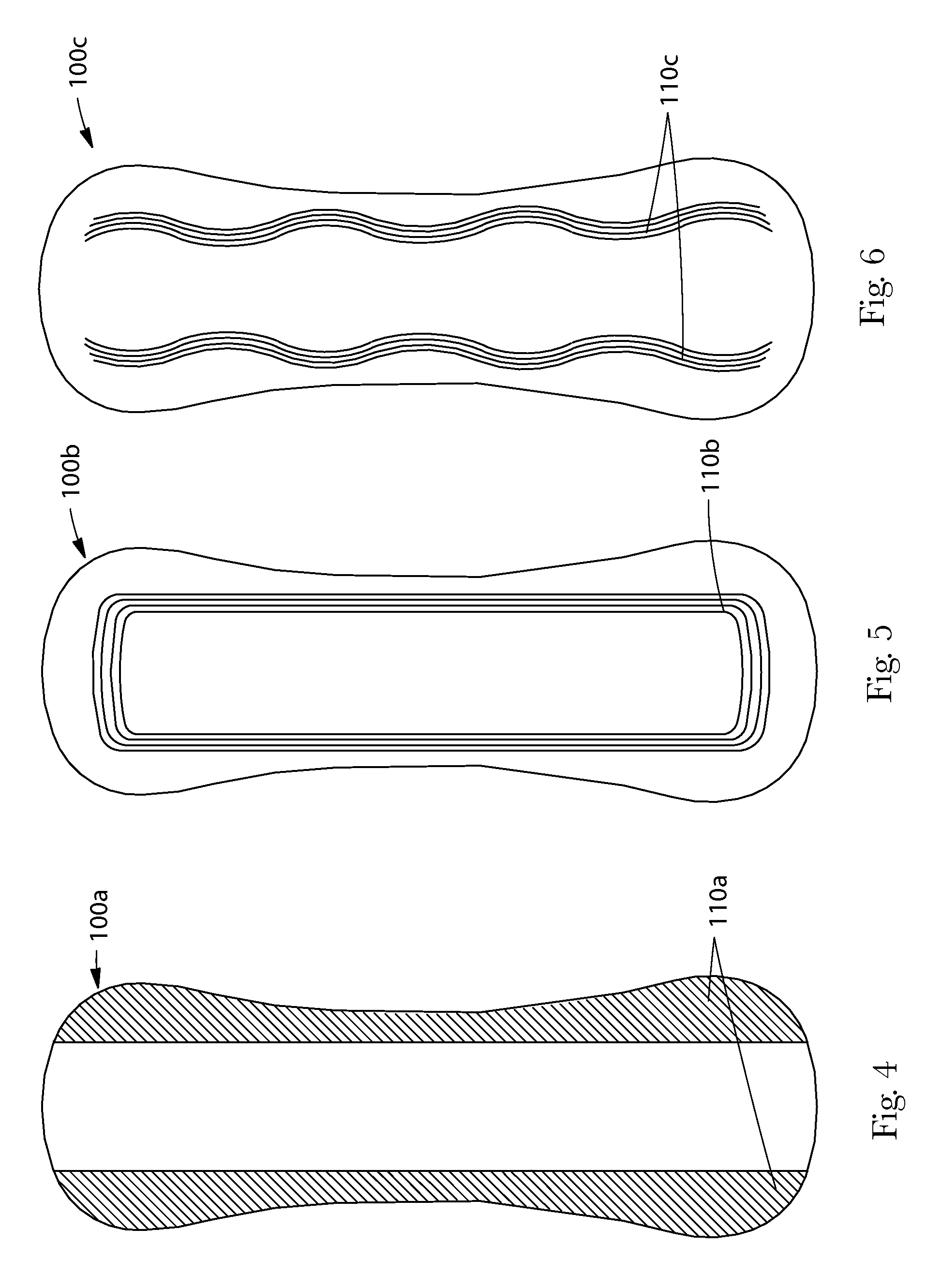
[0006]Methods of producing web substrates comprising activatable colorants where a region of the web substrate is heated prior to activating the activatable colorant such that exposing the web substrate to electromagnetic radiation produces a first activated color region in the heated region and a second activated color region in a region that is not heated prior to activating the activatable colorant. The first and second activated color regions can have the same or different color but the first activated color region has a different shade than the second activated color region. The web substrate can be heated prior to activating the activatable colorant via a heated nip or alternatively during formation of apertures in the web substrate where the heated regions circumscribe the apertures. Alternatively, the web substrate can be heated during the formation of bond sites where the heated regions coincide with the bond sites. Alternatively, the web substrate can be heated during application of a heated topical additive. The heated topical additives can include lotions, hot melt adhesives, coatings, odor control compositions and perfumes.

Problems solved by technology

Such equipment can represent a significant capital cost to manufacturing.
Adding printing capability to the manufacturing process in order to highlight the deformed regions or regions including topical additives represents an additional capital cost and complexity in order to register the printing with the deformed regions and / or regions including the topical additive.
In some instances, the approach manufacturers have chosen to provide for colored regions might not be easily adapted in order to provide for colored regions that coincide with other regions due to the crowded nature of the manufacturing line.
Thus, if a manufacturer desires to provide for visual elements on deformed regions or regions of the absorbent article including topical additives, the manufacturer might have to retool the manufacturing line to provide for additional printing and registration capabilities, thus incurring significant additional capital cost.

Method used


Image

  • Method of producing color change in a substrate
  • Method of producing color change in a substrate
  • Method of producing color change in a substrate

Examples


example 1

Impact of Pre-Heating Step on Color After UV Activation

[0166]A spunbond nonwoven fabric was prepared comprising polypropylene and 1 weight percent Datalase Colour Change Pigment LT (from Datalase Ltd., Widnes, UK). Basis weight of the nonwoven is 28 grams per square meter. As made, the nonwoven is white.

[0167]Handsheets of this material were exposed to ultraviolet light in a Chromato-Vue C-75 UV darkroom cabinet set to 254 nm with an exposure time of 1 minute. The fabric turned a pale blue color. A second set of handsheets were passed through a laminator set to a temperature of 255° F. to uniformly heat the material. The handsheets were subsequently exposed to ultraviolet light under the same conditions as described above. The fabrics turned a darker shade of blue than the first set of materials. Color measurements, ΔC and ΔE values are provided in Table 1. The sample that had been pre-heated prior to UV activation has a significantly darker shade than the sample that underwent UV a...

example 2

Patterned Preheating Via Heated Nip and Masking

[0168]The same nonwoven as described in Example 1 was masked with a pattern of joining circles laser cut into a piece of paper. The nonwoven and paper were run together through a heated nip (laminator) at 124° C., masking some of the nonwoven from the heat of the nip roll. The paper mask was removed and the nonwoven then exposed to ultraviolet light in a Chromato-Vue C-74 darkroom cabinet set to 254 nm for 30 seconds. The entire nonwoven turned blue, but the shade of blue was darker in regions that were previously exposed to heat and lighter in regions that were masked from the heat. A black and white photograph of the resulting sample is provided in FIG. 11.

example 3

Preheating Via Ultrasonic Bonding

[0169]The same nonwoven as described in Example 1 was ultrasonically bonded to add a secondary bonding pattern using a Branson 900 model scan bonder and an acid etched bonding plate. After the bonding process, the material was still uniformly white in color. The material was then exposed to ultraviolet light in a Chromato-Vue C-74 darkroom cabinet set to 254 nm for 30 seconds. The entire nonwoven turned blue, however the secondary bond sites were a darker shade of blue than the surrounding nonwoven. A black and white photograph of the sample is provided in FIG. 12


PUM

PropertyMeasurementUnit
diametersaaaaaaaaaa
diametersaaaaaaaaaa
diametersaaaaaaaaaa

Abstract

The present invention relates to a method of producing color change in a substrate. The substrate includes an activatable colorant and a region that is heated prior to activating the activatable colorant. The substrate is exposed to electromagnetic radiation producing a first activated color region in the heated region and a second activated color region in a non heated region. The first activated color region appears in a different shade than the second activated color region.

Description

FIELD OF THE INVENTION[0001]The present invention is related to activatable colorants that are activated to produce color. Specifically, the invention is related to a method of producing color change in substrates comprising activatable colorants where the substrate includes regions that are heated prior to activating the activatable colorants such that the colors of the heated regions appear in a different contrast than the non heated regions.BACKGROUND OF THE INVENTION[0002]A variety of absorbent articles that include different colored regions are available in the market. For instance, absorbent articles such as sanitary napkins and female adult incontinence articles that function to collect fluid discharged from a woman's vagina or urethra sometimes include colored regions to highlight various sections of the absorbent article. For instance the topsheet of the absorbent article may include deformed regions such as apertures proximal the central portion of the absorbent article th...

Claims


Application Information

Patent Timeline
Patent Type & Authority Applications(United States)
IPC IPC(8): G03C5/00
CPCA61F13/513D06P1/0096A61F13/84A61F2013/15243A61F2013/51377A61F2013/8497B41M5/282B41M5/285D01F1/04D06P1/004D06P5/2005G03C1/73G03C1/7642D06P5/12D06P5/2066A61F13/51496
Inventor MULLANE, TIMOTHY IANARORA, KELYN ANNE
Owner THE PROCTER & GAMBLE COMPANY
Learn More