Color-change material layer

a technology of color-changing materials and layers, applied in the direction of discharge tubes/lamp details, organic semiconductor devices, discharge tubes luminescnet screens, etc., can solve the problems of limited resolution and size, limited design efficiency, and current technology, such as the use of shadow masks, to achieve the effect of improving the light output and sharpness of light-emitting devices

Active Publication Date: 2011-06-28
GLOBAL OLED TECH
View PDF28 Cites 115 Cited by
  • Summary
  • Abstract
  • Description
  • Claims
  • Application Information

AI Technical Summary

Problems solved by technology

However, such patterning is difficult and expensive and current technologies, such as the use of shadow-masks, are limited in resolution and size.
However, such designs are relatively inefficient since approximately two-thirds of the light emitted may be absorbed by the color filters.
In general, color-change material systems suffer from efficiency problems.
The production of relatively higher-frequency blue light can be difficult and the conversion of light from relatively higher frequencies to relatively lower frequencies may not be efficient or the conversion materials may fade over time, reducing the performance of the display.
Moreover, much of the relatively higher-frequency light may not interact with the color-change materials and thus may not be converted to the desired, relatively lower frequency light.
However, the efficiency of emitted-light conversion remains a problem.
It has also been found, that one of the key factors that limits the efficiency of OLED devices is the inefficiency in extracting the photons generated by the electron-hole recombination out of the OLED devices.
Due to the high optical indices of the organic materials used, most of the photons generated by the recombination process are actually trapped in the devices due to total internal reflection.
In general, up to 80% of the light may be lost in this manner.
However, none of these approaches cause all, or nearly all, of the light produced to be emitted from the device.
Moreover, diffractive techniques cause a significant frequency dependence on the angle of emission so that the color of the light emitted from the device changes with the viewer's perspective.
However, as described in U.S. Ser. No. 11 / 065,082, by Cok referenced above, the use of scattering layers without the use of low-index layers results in reduced sharpness in a pixilated device.
Moreover, low-index layers, particularly in bottom-emitter devices, are difficult to build.
Co-pending, commonly assigned U.S. Ser. No. 11 / 387,192, filed Mar. 23, 2006 entitled “OLED Device having Improved Light Output” by Cok which is hereby incorporated in its entirety by reference describes such a bottom-emitter OLED device, but the formation of the low-index elements described therein may be difficult.
Hence, the use of scattering layers in concert with color-change materials is problematic, particularly for bottom-emitter OLED devices.
In the absence of such scattering layers, prior-art solutions incorporating color-change materials for extracting trapped light may not be effective.

Method used


Image

  • Color-change material layer
  • Color-change material layer
  • Color-change material layer

Examples


Embodiment Construction

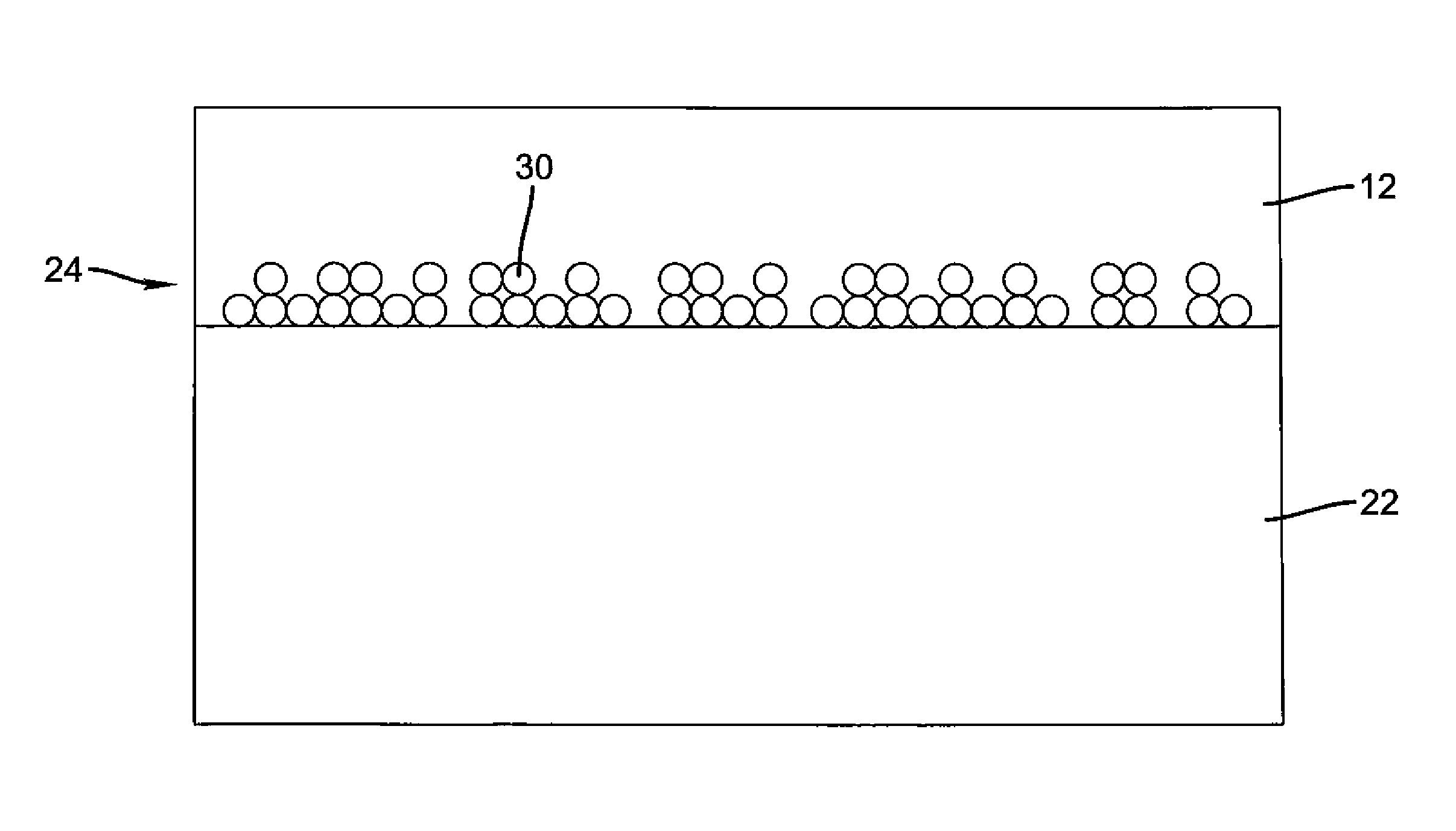
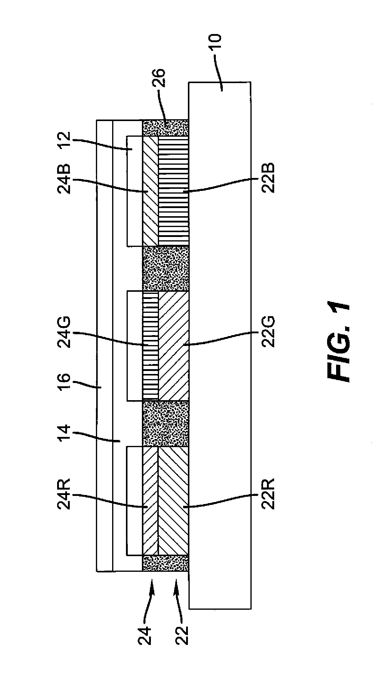
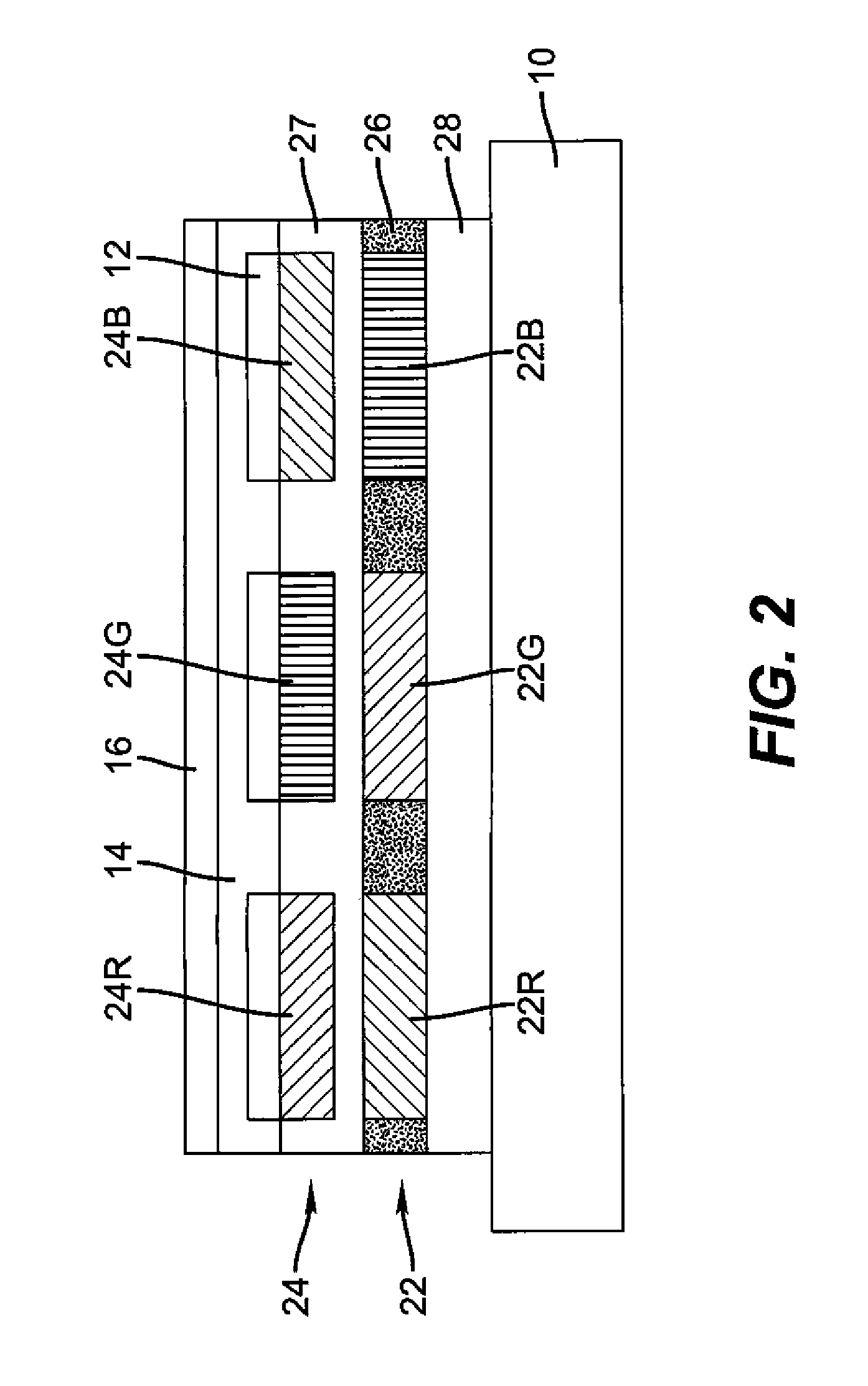
[0022]Referring to FIG. 1, one embodiment of an organic or inorganic LED device according to the present invention comprises a substrate 10, one or more color filters 22 formed above the substrate 10 and transmitting light having a first frequency range, a layer 24 of color-change material formed above the color filter 22 that converts light of a second frequency range higher than the first frequency range to light of the first frequency range, a first transparent electrode 12 formed adjacent to the color-change material layer 24; one or more layers 14 of organic material formed over the transparent electrode 12, at least one of which emits light in at least the second frequency range in response to a current passed there-through; and a second electrode 16 formed over the one or more organic layers 14. The color-change material layer 24 is substantially non-scattering to light of the first frequency range, and additionally comprises a transparent material having a refractive index o...


PUM


Abstract

A color-change material layer comprising: a color-change material that converts light of a second frequency range higher than a first frequency range to light of the first frequency range; and a transparent material having a refractive index of at least 1.6 intermixed with the color-change material, wherein the layer is substantially non-scattering to light of the first frequency range.

Description

FIELD OF THE INVENTION[0001]The present invention relates color change material layers, and more particularly to use of such layers in an organic or inorganic LED display device, and further to device structures for improving the efficiency of such display devices employing broadband emitters and color filters.BACKGROUND OF THE INVENTION[0002]Flat-panel organic LED display devices employ a variety of technologies for emitting patterned, colored light to form full-color pixels. In one approach, different materials emitting light of different colors in response to a current are patterned over a surface. However, such patterning is difficult and expensive and current technologies, such as the use of shadow-masks, are limited in resolution and size. In an alternative approach, a common light-emitter is employed for all of the pixels. One such design relies upon a white-light emitting common organic layer in combination with color filters, for example red, green, and blue, to create a fu...

Claims


Application Information

Patent Timeline
Patent Type & Authority Patents(United States)
IPC IPC(8): H01J1/62H01J63/04
CPCB82Y20/00B82Y30/00H01L27/322H05B33/22H01L33/44H01L51/5206H01L51/5262H01L2251/5369H01L33/50H01L33/58H10K59/38H10K2102/331H10K59/879H10K59/8051H10K59/875H10K50/81H10K50/85
Inventor COK, RONALD S.
Owner GLOBAL OLED TECH
Why Eureka
Try Eureka