Collapsible Horizontal Axis Wind Generator

a horizontal axis, wind generator technology, applied in the direction of electric generator control, machines/engines, sustainable buildings, etc., can solve the problems of large and expensive wind generators, hawg generators, and wind generators that are available today, so as to maximize the amount of electrical energy reduce the exposure of the number of blades to shear stressors produced by the wind, and reduce the effect of the number of blades

Inactive Publication Date: 2012-09-27
AGTUCA PETE
View PDF2 Cites 20 Cited by
  • Summary
  • Abstract
  • Description
  • Claims
  • Application Information

AI Technical Summary

Benefits of technology

[0013]During low winds (3 to 15 mph), both sets of rotors may be extended thereby maximizing the amount of electrical energy produced by the wind. During moderate winds (16 to 25 mph), at least one set of blades on one rotor assembly is collapsed and the other set of blades on the other rotor assembly is extended thereby reducing the number blades exposure and to shear stressor produced by the wind. During high winds (above 25 mph), the sets of blades on both rotor assemblies are collapsed thereby protecting the entire system.

Problems solved by technology

Unfortunately, wind generators available today use large and expensive turbine generators mounted at a fixed position on the end of a large pole or tower.
Obviously one drawback with HAWG generators is that they must be stopped during high winds.
Another drawback is that HAWG generators are large structures that require large supporting poles or towers to hold the generator and blades in an elevated position above the ground and away from other objects.
Because of their size, they are difficult to install, visually obtrusive and expensive.
They are not well suited for low wind environments, densely populated areas, scenic viewing areas, or in areas where the direction of the wind varies greatly.

Method used


Image

  • Collapsible Horizontal Axis Wind Generator
  • Collapsible Horizontal Axis Wind Generator
  • Collapsible Horizontal Axis Wind Generator

Examples


first embodiment

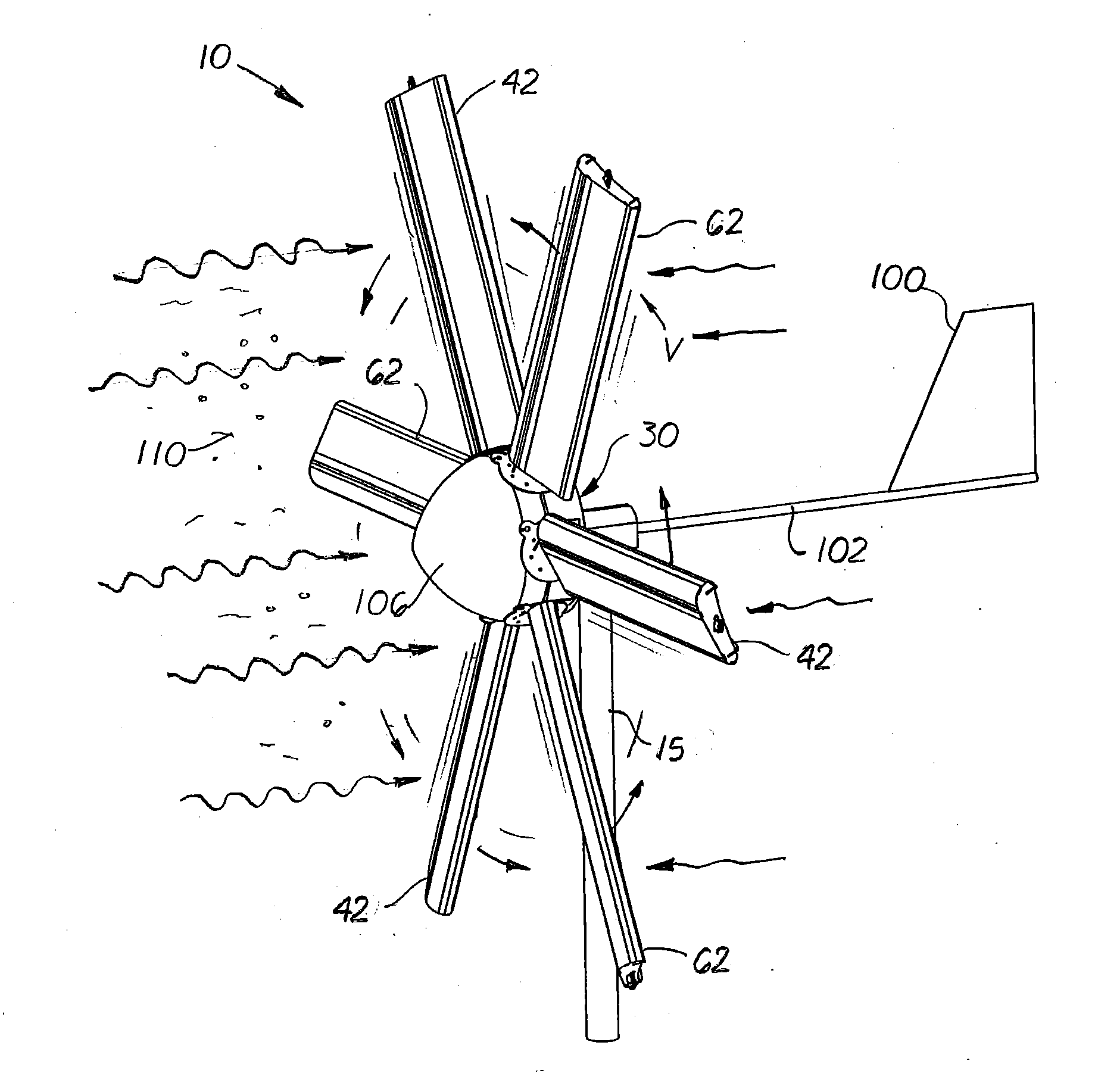
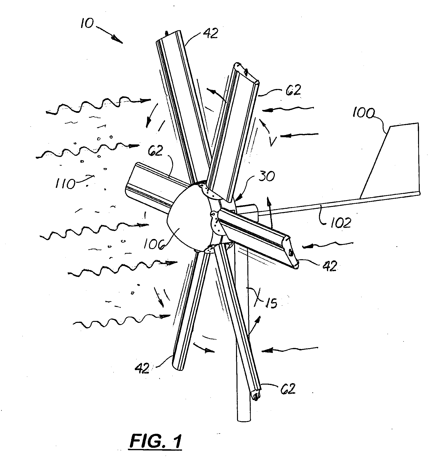
[0041]The blades 42 and 62 are designed to product sufficient torque to rotated the generator. In the first embodiment, shown in FIGS. 7 and 8, the blades 42, 62 are identical is size and structure and have an airfoil cross-sectional shape with a rounded leading edge 46 and a thin tailing edge 48. Each blade (only blade 42 is shown in FIG. 8 but should be understood to also describe blade 62) includes a lower mounting plate 50 that attaches to the perimeter edge of the rotor plate 70. Aligned perpendicular and extending outward from each lower mounting plate 50 are three fixed rods 52, 53, 54. Aligned perpendicularly and mounted on the ends of the three rods 52, 53, 54 is outer frame plate 56. Mounted centrally and extending outward from the outer frame plate 56 is a pulley 58. Formed on the outer frame plate 56 on opposite sides of the pulley 58 are two bores through which a semi-rigid cable 75 extends.

[0042]Each blade 42 also includes a transversely aligned upper guide plate 47 th...

second embodiment

[0050]During use, the wind generators may be aligned so that the wind flows directly against the longest side of the blades 42, 62 or against the outside surface of the blades 242, 262. It should be understood however, that with the second embodiment, the blades 242 and 262 may be rotated 180 so that the inside surface of the flexible panel 280 is in direct contact with the wind causing the flexible panel 280 to operate like a sail.

[0051]As shown in FIG. 13, an addition used of the second embodiment of the generator 200 is as a sign or a display. In the second embodiment of the generator 200, the advertising indicia, generally indicated by the reference number 400 may be printed on one or both surfaces of the flexible panel 280 which is viewable when to nearby observers when the blades 242 are unfurled and the rotor assemblies 240 and 260 are stationary. During use, when the wind is too low to rotated the generator 30, the rotor assemblies 240, 260 are rotated on the vertical pole a...


PUM


Abstract

A low wind, lightweight horizontal axis wind generator with two adjustable rotor assemblies that include at least one set of lightweight blades that can be manually or automatically unfurled or furled in low, moderate and high winds. In one embodiment, each blade has an airfoil shape in cross-sectional with a rounded leading edge and a thin tailing edge. In a second embodiment, each blade is sail shaped made of one thin cover or panel that assumes a concave cup-like configuration in the wind. In both embodiments, the blade are made of lightweight flexible material supported by an inner frame. In one embodiment, the cover moves longitudinally over the inner frame. In the second embodiment, the cover moves laterally over the inner frame. The unfurling and furl of the blades are controlled by a voltage sensor that constantly measures the voltage output of the generator and/or by wind sensors.

Description

[0001]This utility patent application is based on and claims the filing date benefits of U.S. provisional patent applications (61 / 355,314, filed Jun. 16, 2010) and (61 / 425,628, filed Dec. 21, 2010).[0002]Notice is hereby given that the following patent document contains original material which is subject to copyright protection. The copyright owner has no objection to the facsimile or digital download reproduction of all or part of the patent document, but otherwise reserves all copyrights whatsoever.BACKGROUND OF THE INVENTION[0003]1. Field of the Invention[0004]This invention pertains to wind generators, and more specifically to scalable wind generators used in low to high velocity winds.[0005]2. Description of the Related Art[0006]Wind power is widely accepted as an environmental friendly means for producing energy. Unfortunately, wind generators available today use large and expensive turbine generators mounted at a fixed position on the end of a large pole or tower. Horizontal ...

Claims


Application Information

Patent Timeline
Patent Type & Authority Applications(United States)
IPC IPC(8): H02P9/04
CPCF03D1/0675F03D7/0236Y02E10/723Y02B10/30Y02E10/721H02P9/04Y02E10/72
Inventor AGTUCA, PETE
Owner AGTUCA PETE
Why Eureka
Try Eureka