Electric machine excited by permanent magnets

a technology of electric machines and permanent magnets, applied in the direction of rotating magnets, synchronous machines with stationary armatures, dc commutators, etc., can solve the problem of limited power density of electric machines

Inactive Publication Date: 2012-09-27
COMPACT DYNAMICS
View PDF4 Cites 4 Cited by
  • Summary
  • Abstract
  • Description
  • Claims
  • Application Information

AI Technical Summary

Problems solved by technology

Such electric machines have a limited power density.

Method used


Image

  • Electric machine excited by permanent magnets
  • Electric machine excited by permanent magnets
  • Electric machine excited by permanent magnets

Examples


Embodiment Construction

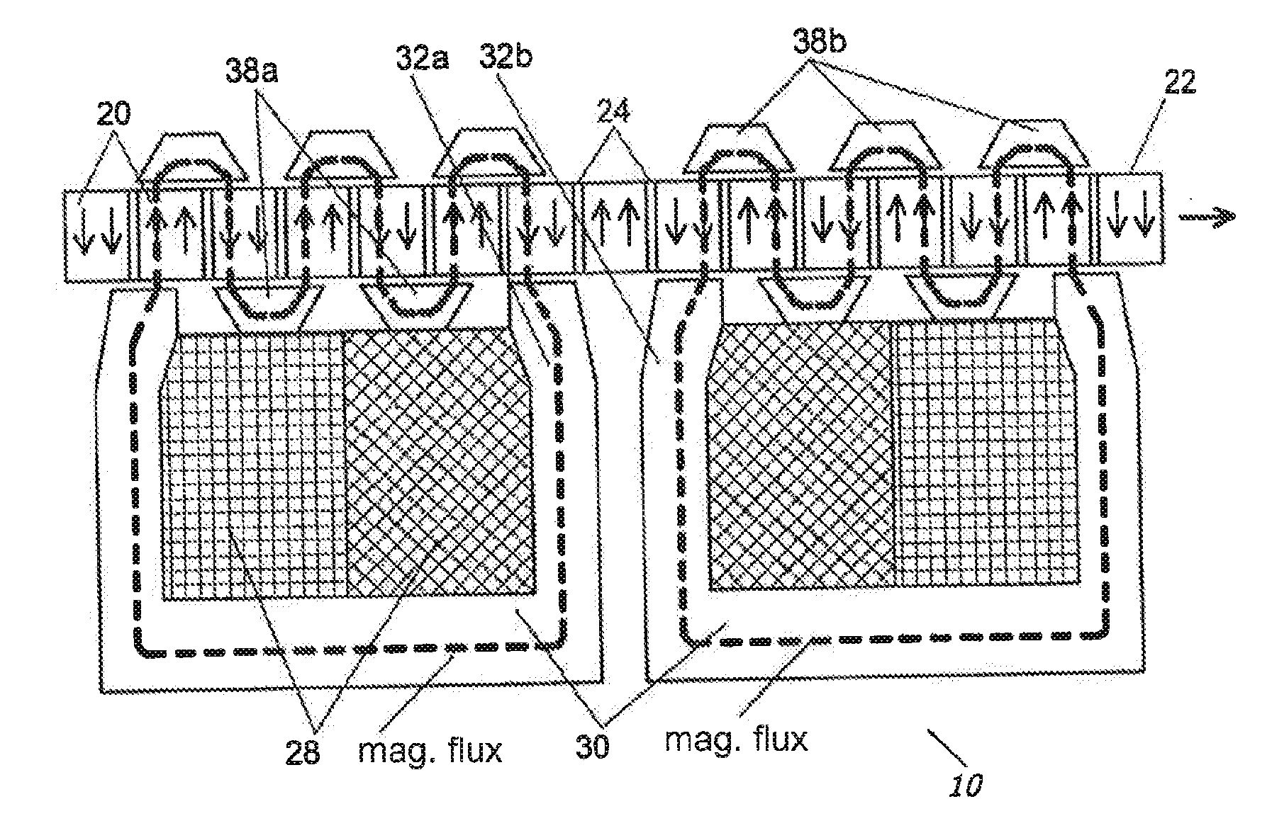
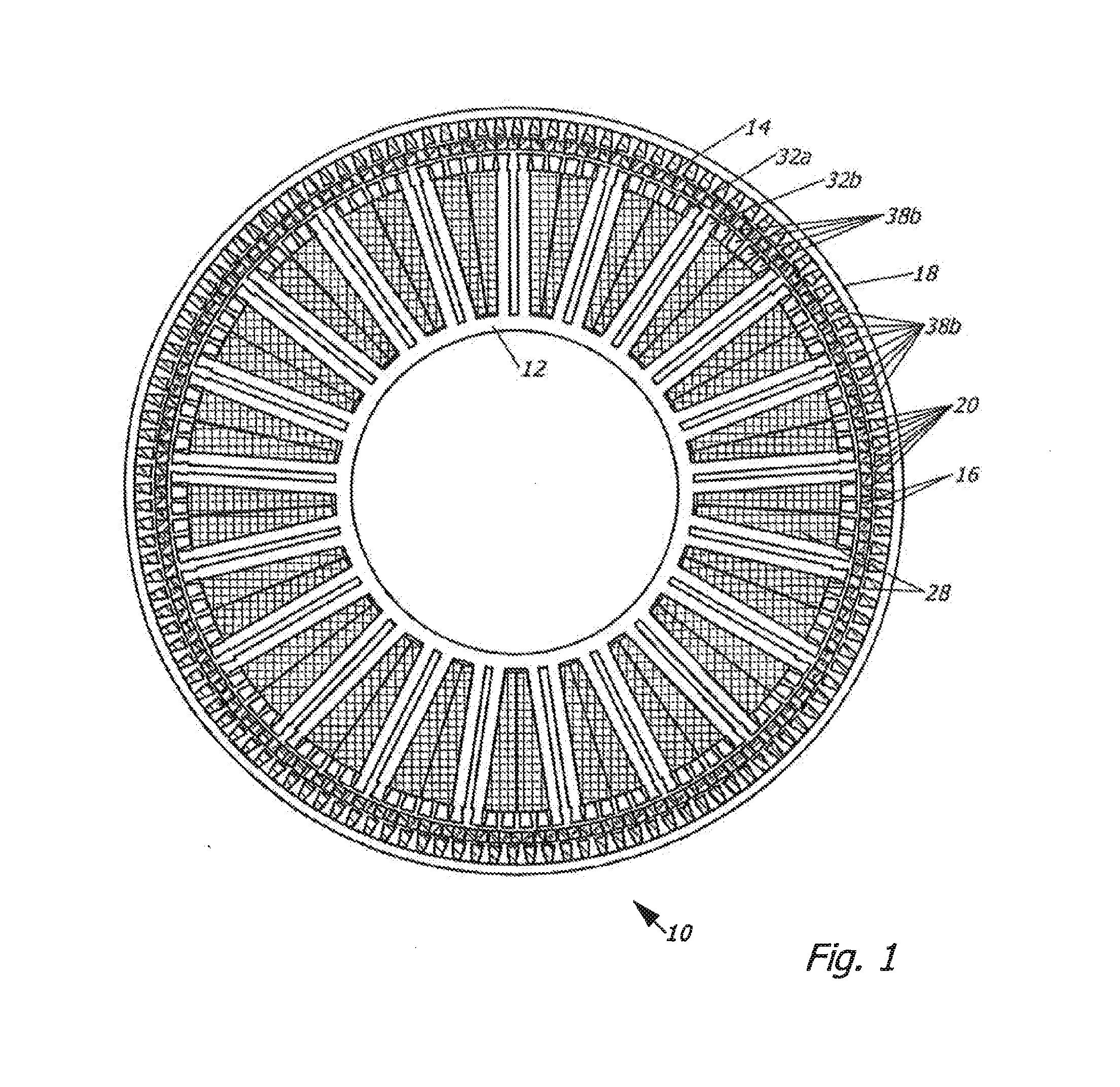
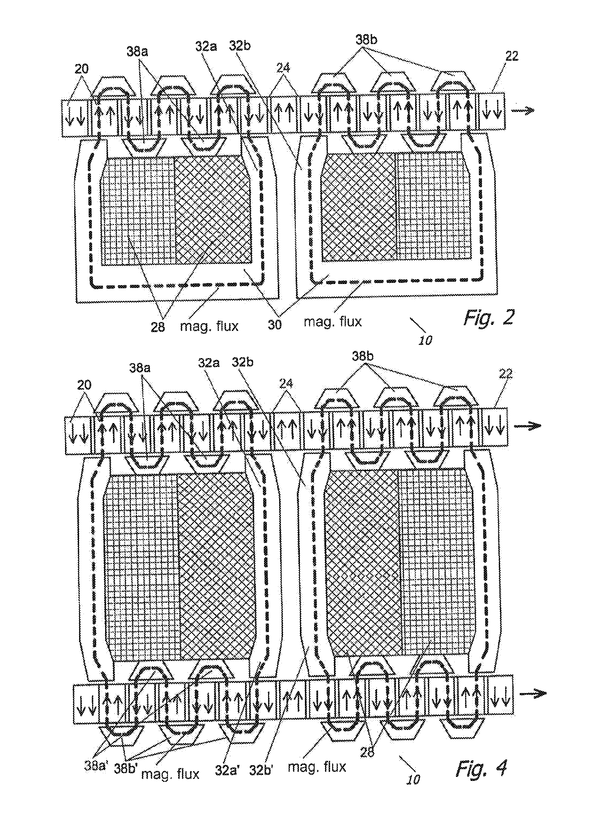
[0033]FIG. 1 shows a cross section through an embodiment of an electric machine 10 excited by permanent magnets, which is designed as an external-rotor machine. The principle on which this machine is based can also be used for an internal-rotor machine. The transversal flux machine 10 has a stator 12 and a rotor 14. An air gap 16 is formed between the rotor 14 and the stator 12. The stator 12 is accommodated in a tubular housing 18, which, at each of its two outside ends, has a bearing, not shown, for receiving a drive / output shaft, not shown. The drive / output shaft is connected to the rotor 14 in a rotationally fixed manner, not shown.

[0034]In this variant, the stator 12 has a coil arrangement 28. The rotor is provided with a plurality of permanent-magnet elements 20. Permanent-magnet elements 20 that are adjacent to each other have opposing magnetic orientations in each case. The permanent-magnet elements 20 are combined to form a magnet disc 22. In the case of a linearly moving m...


PUM


Abstract

In order to provide a compact and highly efficient electric machine having high power density, an electric machine excited by permanent magnets, comprising a stator and a rotor, is provided. The stator comprises a coil arrangement and the rotor has permanent magnet elements. The coil arrangement comprises a winding and surrounds a flux yoke. The flux yoke comprises at least one limb. Between every two limbs, flux guide parts are arranged that are spaced apart from each other and that are aligned with the ends of the limbs. Neighbouring permanent magnet elements have opposing magnetic orientations and are combined to form a magnet disc. On the side facing away from the limbs of the permanent magnet elements, flux guide parts are arranged. The limbs and the flux guide parts face the permanent magnet elements forming an air gap.

Description

TECHNICAL FIELD [0001]Presented here is an electric machine excited by permanent magnets. This machine has a stator and a rotor, the stator comprising a stator coil and the rotor being provided with permanent-magnet elements, or the rotor comprising a rotor coil and the stator being provided with permanent-magnet elements.[0002]Known from EP 0 218 522 A1 is a synchronously excited electric machine having C-shaped magnetic flux yokes and having magnetic-flux guide pieces, which are disposed in axial rows and which are at least partially in alignment with permanent magnets of the rotor.DEFINITION OF TERMS [0003]The term “electric machines excited by permanent magnets” means both motors and generators. It is immaterial in this case whether such a machine is designed as a rotary machine or, for example, as a linear motor. In addition, the invention can be applied both in the case of internal-rotor machines and in the case of external-rotor machines.PRIOR ART [0004]Usually, in the prior ...

Claims


Application Information

Patent Timeline
Patent Type & Authority Applications(United States)
IPC IPC(8): H02K21/02
CPCH02K21/22H02K1/12
Inventor GRUENDL, ANDREASHOFFMANN, BERNHARD
Owner COMPACT DYNAMICS
Why Eureka
Try Eureka