System and Methods for Mitigating Changes in Pupil Size During Laser Refractive Surgery to Maintain Ablation Centration

a technology of ablation centration and laser refractive surgery, which is applied in the field of systems and methods for diagnosing and/or treating vision in, can solve the problems of increasing the cognitive load experienced by the patient during the procedure, affecting the pupil size, and changing the optical distance of the viewing target, so as to improve eye tracking and alignment, the effect of not significantly changing the pupil size and increasing the cognitive load

Active Publication Date: 2012-09-27
AMO DEVMENT
View PDF9 Cites 37 Cited by
  • Summary
  • Abstract
  • Description
  • Claims
  • Application Information

AI Technical Summary

Benefits of technology

[0012]The present invention provides methods and systems which can improve eye tracking and alignment during a diagnostic and / or treatment procedures of the eye, particularly laser eye surgery. Unlike systems which implicitly assume that pupil sizes do not change by clinically significant amounts during a refractive surgery procedure, exemplary embodiments of the present invention anticipate and mitigate significant changes to the pupil during a procedure. It is often assumed that if light levels remain fairly constant, the pupil size will not significantly change. However, pupil size may be affected by other factors, which include: stress, inability of the patient to focus on a target during a procedure, a change in optical distance of the viewing target, and an increase in cognitive load experienced by the patient during the procedure. An increase in cognitive load may result from accessing memory, increasing attention or concentration, sensory discrimination, or extreme emotional situations. For instance, fear experienced by a patient undergoing surgery may result in increased cognitive load causing the pupils to dilate. The pupils can also dilate in response to pain or contact of a sensory nerve, both of which may be experienced (to at least some extent) by a patient during a laser eye surgical procedure. These changes in pupil size will also often affect other characteristics of the pupil and the eye, such as pupil center location and iris texture. By anticipating and / or mitigating the dilations and contractions of the pupil (and associated pupil center shifts relative to static ocular landmarks of up to 0.5 mm or more depending on the change in the pupil diameter), the related negative impacts on tracking systems (particularly systems that track cyclorotational movement of the eye by registering a pupil center location or iris features relative to the cornea) can be decreased and / or avoided altogether. Similarly, tracking mechanisms that rely on the pupil position to steer the laser beam during laser refractive surgery and for which the pupil center position shifts relative to the cornea during the surgery, inhibiting changes in the size of the pupil may help avoid the targeted ablation center shifting as well as the resulting suboptimal results. Torsional eye trackers that rely on iris features to track the cornea during a procedure may benefit by anticipating and / or inhibiting dilations and contractions of the pupil during a laser eye surgical treatment, which cause changes to the iris which would otherwise make it more difficult to track the cornea and potentially lead to sub-optimal results.

Problems solved by technology

However, pupil size may be affected by other factors, which include: stress, inability of the patient to focus on a target during a procedure, a change in optical distance of the viewing target, and an increase in cognitive load experienced by the patient during the procedure.
For instance, fear experienced by a patient undergoing surgery may result in increased cognitive load causing the pupils to dilate.
Torsional eye trackers that rely on iris features to track the cornea during a procedure may benefit by anticipating and / or inhibiting dilations and contractions of the pupil during a laser eye surgical treatment, which cause changes to the iris which would otherwise make it more difficult to track the cornea and potentially lead to sub-optimal results.

Method used


Image

  • System and Methods for Mitigating Changes in Pupil Size During Laser Refractive Surgery to Maintain Ablation Centration
  • System and Methods for Mitigating Changes in Pupil Size During Laser Refractive Surgery to Maintain Ablation Centration
  • System and Methods for Mitigating Changes in Pupil Size During Laser Refractive Surgery to Maintain Ablation Centration

Examples


Embodiment Construction

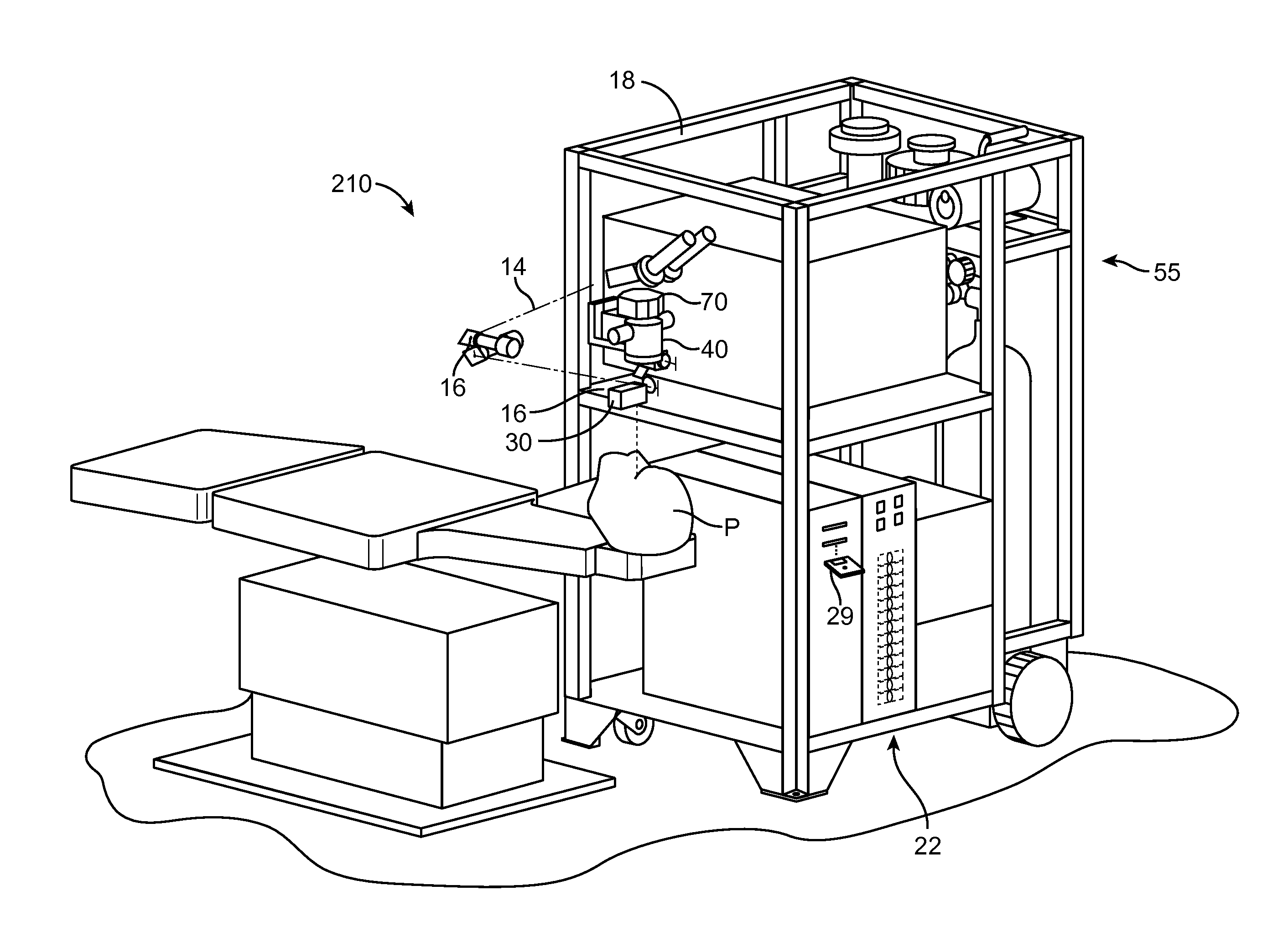
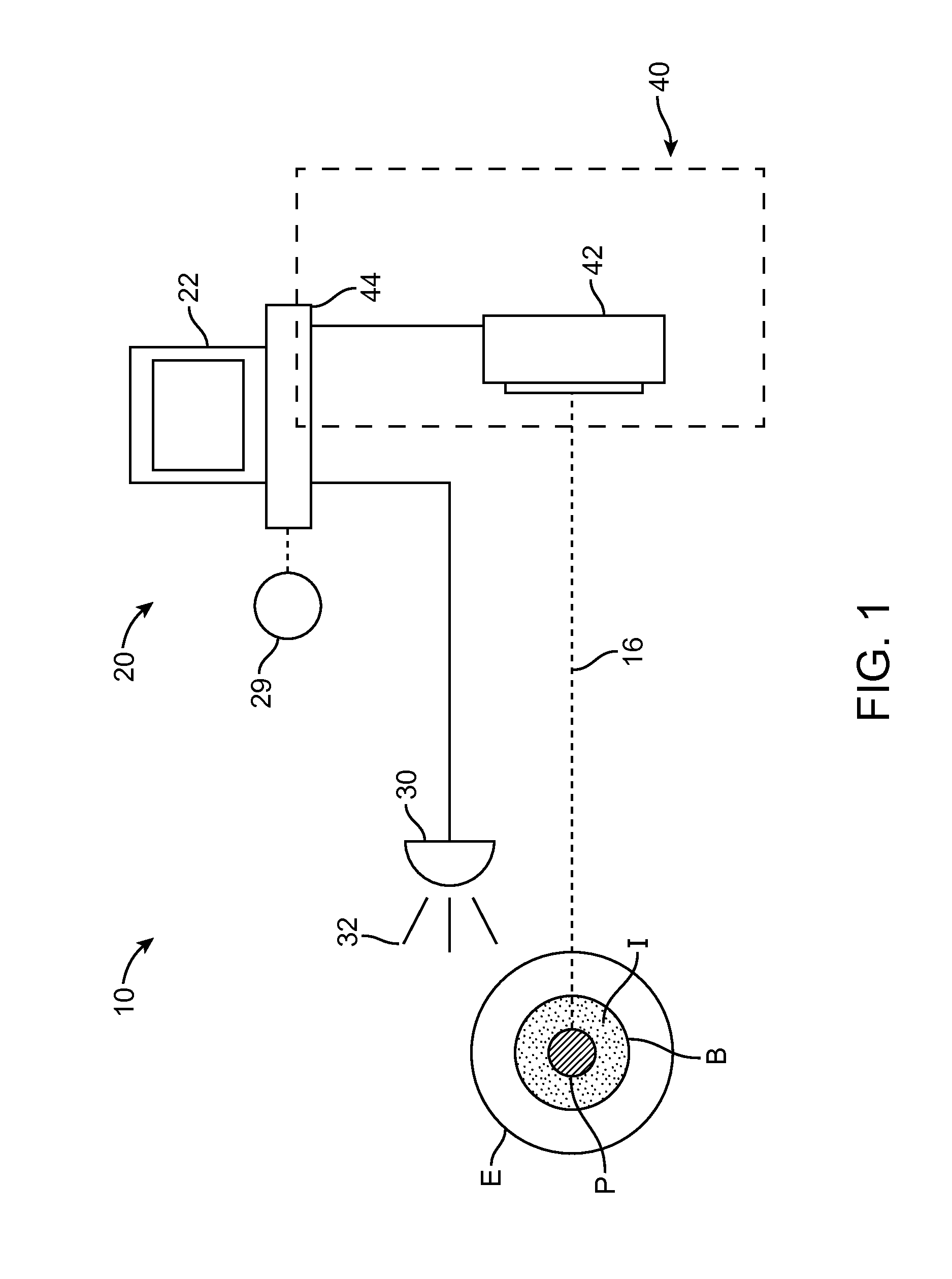
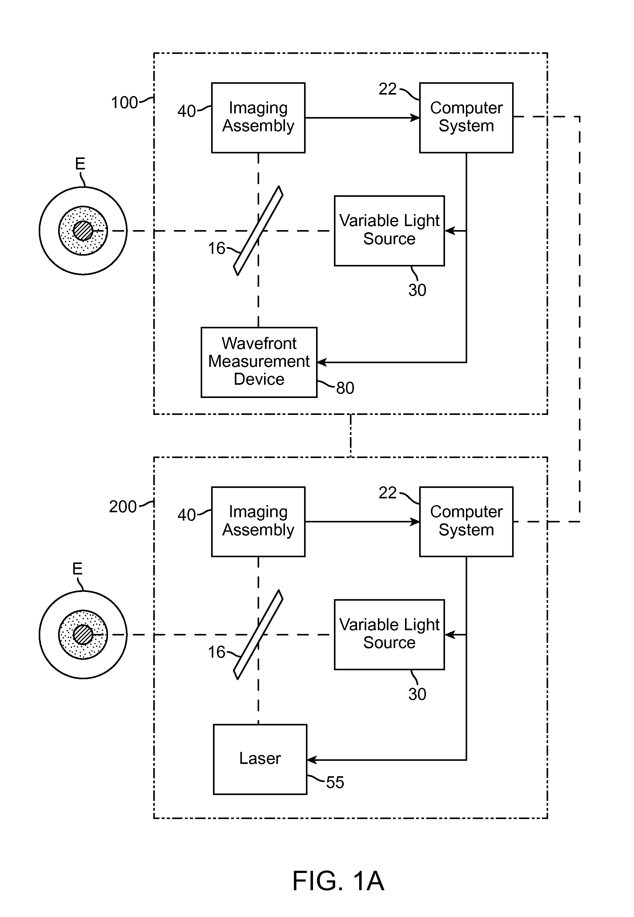
[0036]The present invention generally provides improved devices, systems, and methods for mitigating changes in pupil size during a diagnostic and / or treatment procedure of the eye, particularly during laser eye surgery procedures. In an exemplary embodiment, the invention provides a pupilometer capable of identifying changes in pupil size, an illumination source having a variable optical light output, and a processor. The pupilometer often calculates changes in pupil size, typically by comparing a time-sequence of images of the eye obtained by an image capture device. In response to the calculated change in pupil size, the processor determines a desired optical light output sufficient to induce a desired pupillary response so as to mitigate the calculated change in pupil size. The processor then sends command signals to the variable optical output which directs the desired optical light output to the eye so as to induce the desired pupillary response. Ideally, this process is perfo...


PUM


Abstract

Devices, systems, and methods perform diagnostic and/or treatment procedures on an eye using a pupilometer to determine a change in pupil size, a processor and a variable illumination source. In response to a change in pupil size as determined by the pupilometer, the processor may determine an optical light output sufficient to induce a pupillary response and mitigate the change in pupil size. The system directs the desired optical light output to the eye with the variable illumination source optionally to prevent the pupil size from exceeding certain limits so as to improve torsional tracking of markers of the eye.

Description

CROSS-REFERENCES TO RELATED APPLICATIONS[0001]The present application is a non-provisional of, and claims the benefit of U.S. Provisional Patent Application No. 61 / 384,411, filed Sep. 20, 2010, the entire contents of which are incorporated herein by reference.[0002]The present application is generally related to the following commonly-owned applications: U.S. Ser. No. 12 / 197,774 filed Aug. 25, 2008 (U.S. Pat. No. 7,708,405); U.S. Ser. No. 11 / 088,010 filed Mar. 22, 2005 (U.S. Pat. No. 7,431,455); U.S. Ser. No. 12 / 731,959 filed Mar. 25, 2010; U.S. Ser. No. 09 / 545,240 filed Apr. 7, 2000 (U.S. Pat. No. 6,322,216); and U.S. Ser. No. 10 / 300,714 filed Nov. 19, 2002 (U.S. Pat. No. 7,044,602); the disclosures of which are incorporated herein by reference in their entireties.BACKGROUND OF THE INVENTION[0003]1. Field of the Invention[0004]The present invention is generally related to systems and methods for diagnosis and / or treating vision in a patient. Embodiments of the invention encompass t...

Claims


Application Information

Patent Timeline
Patent Type & Authority Applications(United States)
IPC IPC(8): A61B3/113
CPCA61B3/112A61F2009/00846A61F9/00804A61B5/0077
Inventor CHERNYAK, DIMITRI
Owner AMO DEVMENT
Why Eureka
Try Eureka