Breathable gel
- Summary
- Abstract
- Description
- Claims
- Application Information
AI Technical Summary
Problems solved by technology
Method used
Image
Examples
example 1
[0062]A mold 40 (see FIG. 4) is formed by machining cavities 44 into a body 42, which may be a metal or polymer plate. A top plate is formed such that, when the top plate is fitted to the mold, each cavity 44 is completely encapsulated (with the exception of the gel input means, such as the runners discussed below in this Example 1).
[0063]A TPE gel is formed by mixing one part by weight SEPTON® 4055 SEEPS polymer, eight parts by weight CARNATION® White Mineral Oil (a 70-weight straight-cut white paraffinic mineral oil, available from Sonneborn, Inc., of Mahwah, N.J.), 0.25% by weight EVERNOX® 76 antioxidant (available from Everspring Chemical, of Taichung, Taiwan), 0.25% by weight EVERFOS® 168 antioxidant (available from Everspring Chemical), and 0.25% by weight Horizon Blue pigment (available from DayGlo Color Corp., of Cleveland, Ohio). The mixture is heated and extruded to melt-blend the TPE gel. The molten TPE gel is then pumped into a piston heated above a melting temperature o...
example 2
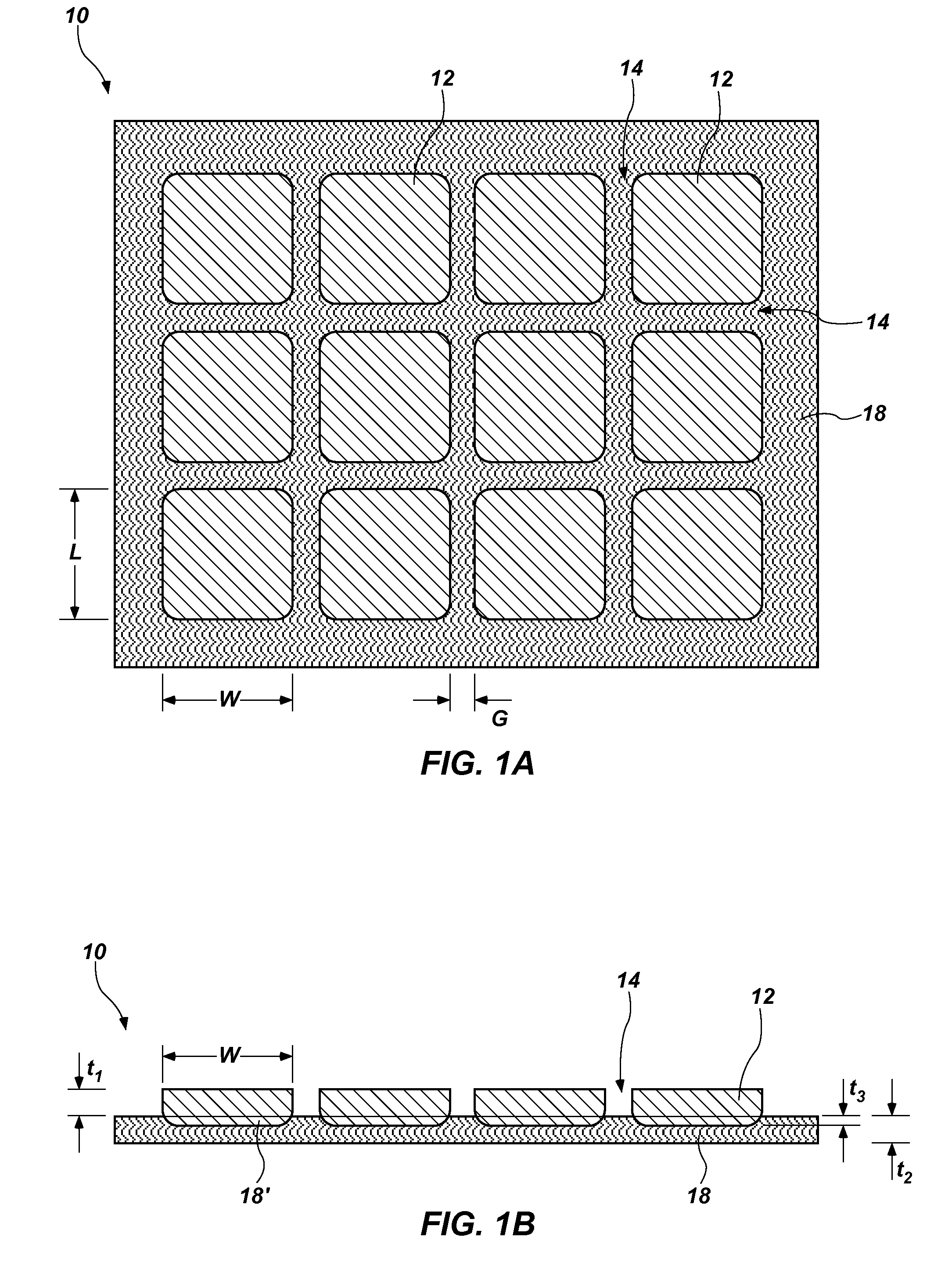
[0066]A mold 40 having an open face is formed as described in Example 1. Molten TPE gel is poured or pressurized into the cavities 44, and excess TPE gel is scraped off (either while still molten or after cooling). Alternatively, TPE gel may be metered into the cavities so that no scraping is necessary. A fabric, foam, or other gel-permeable breathable material 18 is laid onto the TPE gel. Light pressure may be applied to press the breathable material 18 against the TPE gel. If the TPE gel is molten during this process, some of the molten TPE gel may permeate the breathable material 18. If the TPE gel is cooled or solidified prior to placement of the breathable material 18, heat may be applied to melt at least a top portion of the TPE gel. A portion of the melted TPE gel may permeate the breathable material 18. Pressing means may also include heat, for example, a heat press (e.g., a heated plate to press onto the fabric).
example 3
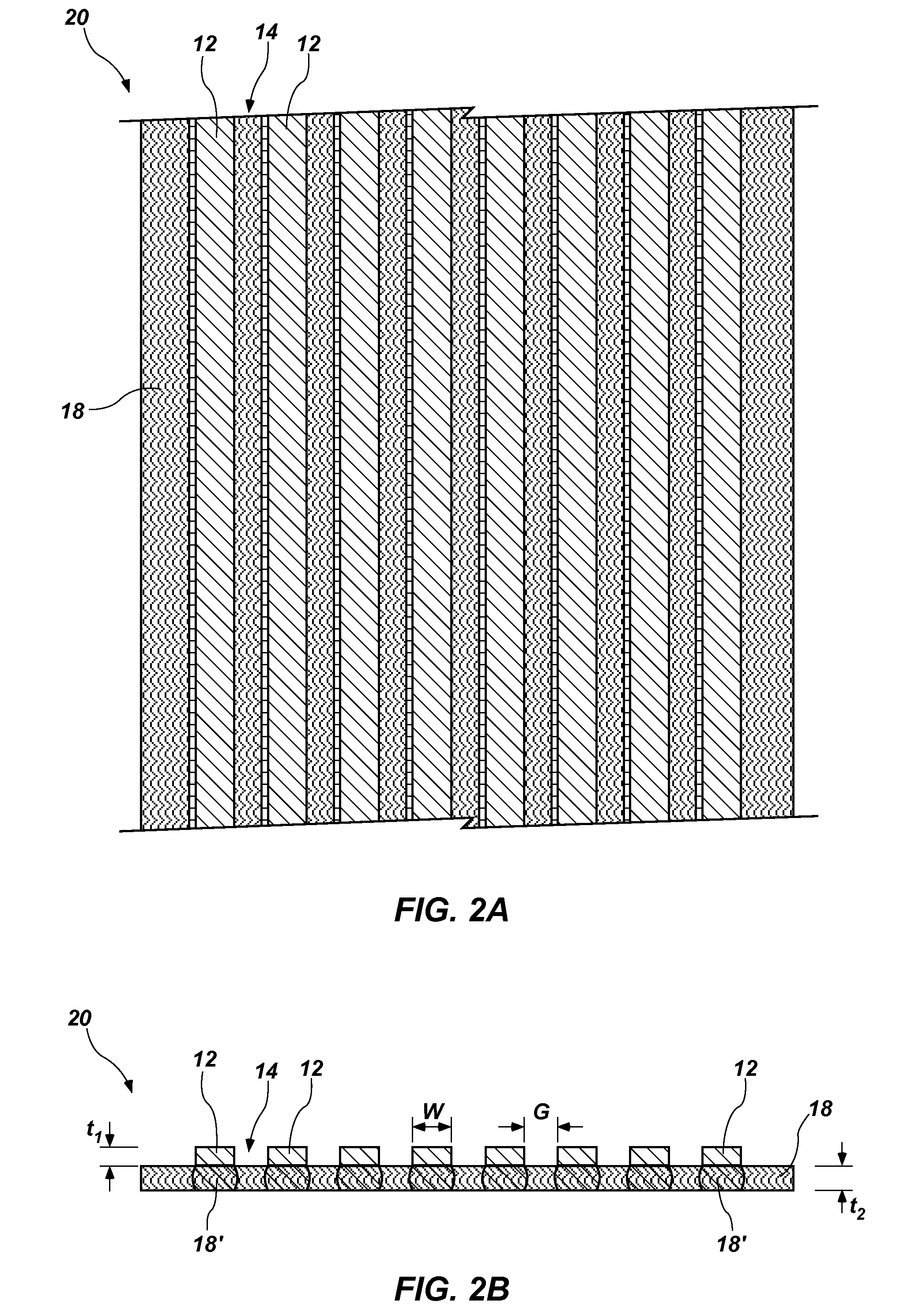
[0067]A mold 40 or a series of molds are as described in Example 2. The breathable material 18 is continuous, and the mold(s) 40 are removed from the breathable material 18 and then brought again to another part of the breathable material 18. For example, the mold(s) 40 may include a tank-tread style set of molds that are connected in a continuous circular configuration that continuously cycles under the unrolling breathable material 18, or may include a rotating drum. The mold(s) 40 may be flooded with molten TPE gel at one point on the mold rotation, followed downstream with a scraping means (e.g., a silicone rubber squeegee-type blade or a metal blade, either of which may be heated, cooled, or maintained at room temperature). The breathable material 18 is pressed into the top surface of the TPE gel while the TPE gel is still in the mold cavities. A means of pulling on the breathable material 18 translates the breathable material 18 adjacent the mold(s) 40 and provides a force to ...
PUM
 Abstract
Description
Claims
Application Information
 - R&D
- Intellectual Property
- Life Sciences
- Materials
- Tech Scout
- Unparalleled Data Quality
- Higher Quality Content
- 60% Fewer Hallucinations
Browse by: Latest US Patents, China's latest patents, Technical Efficacy Thesaurus, Application Domain, Technology Topic, Popular Technical Reports.
© 2025 PatSnap. All rights reserved.Legal|Privacy policy|Modern Slavery Act Transparency Statement|Sitemap|About US| Contact US: help@patsnap.com


