Spinning disc centrifuge rotor

a spinning disc and centrifuge technology, applied in the direction of specific gravity using centrifugal effects, measuring devices, instruments, etc., can solve the problems of no spinning disc centrifuge produced that effectively allows such complete measurement and testing, and no centrifuge b>200/b> allows for consolidated samples

Inactive Publication Date: 2012-09-27
KUWAIT UNIV
View PDF8 Cites 5 Cited by
  • Summary
  • Abstract
  • Description
  • Claims
  • Application Information

AI Technical Summary

Benefits of technology

[0015]The spinning disc centrifuge rotor is a transparent laboratory centrifuge rotor and sample holder of the spinning disc type; i.e., adapted for centrifugation of a cylindrical core sample, such as a porous rock sample containing petroleum products, in which rotation occurs about the central cylindrical axis of the sample. The spinning disc-type rotor and sample holder, along with the transparent nature of the rotor, allow for accurate measurements of capillary pressure, relative permeability curves, and other experimental test data commonly associated with such samples.

Problems solved by technology

Porous solids containing liquids provide unique challenges in centrifugation.
This relatively simple arrangement, however, makes both direct measurements and calculated predictions extremely difficult.
Thus far, no spinning disc centrifuge has been produced that effectively allows for such complete measurement and testing.
Further, although such an arrangement is an improvement over the simple system 100 shown in FIG. 2, the centrifuge 200 does not allow for consolidated samples.
Further, performing pressure measurements remains extremely difficult in this arrangement, since the collection vessels 214 are best used solely for collection following the completed centrifugation process.

Method used


Image

  • Spinning disc centrifuge rotor
  • Spinning disc centrifuge rotor
  • Spinning disc centrifuge rotor

Examples


Embodiment Construction

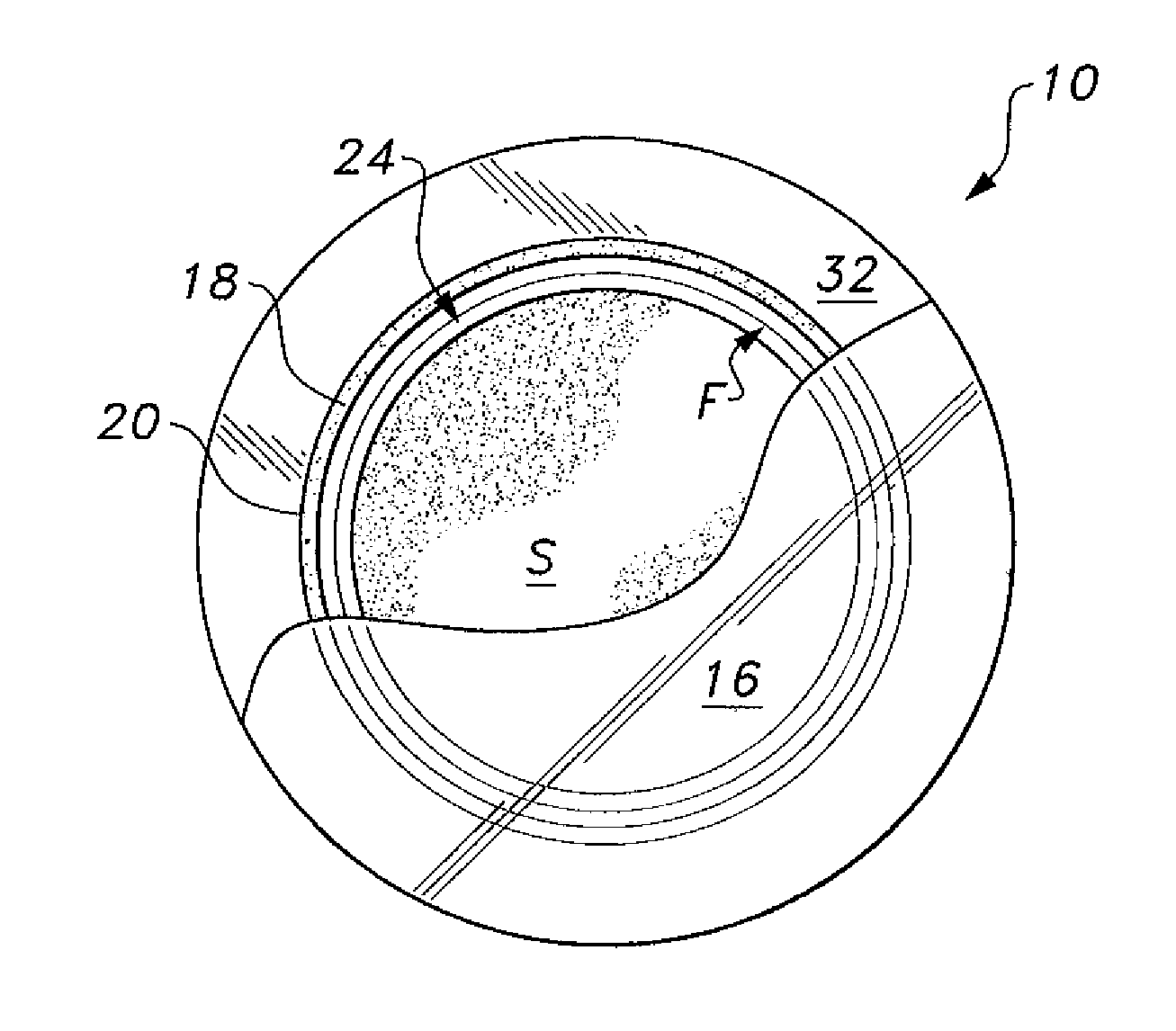
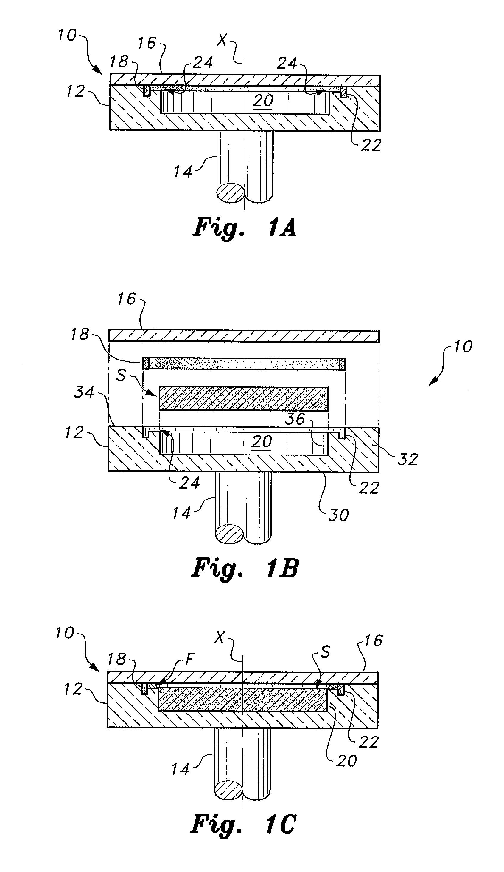
[0029]The spinning disc centrifuge rotor 10 is a transparent laboratory centrifuge rotor and sample holder of the spinning disc type; i.e., adapted for centrifugation of a cylindrical core sample, such as a porous rock sample containing petroleum products, with rotation occurring about the central cylindrical axis of the sample. In FIGS. 1B, 1C and 6, an exemplary cylindrical core sample S is illustrated. It should be understood that core sample S is shown for exemplary and illustrative purposes only. As will be described in greater detail below, the geometry and construction of the spinning disc-type rotor 10, along with the transparent nature of the rotor, allow for accurate measurements of capillary pressure, relative permeability curves, and other experimental test data commonly associated with such samples.

[0030]As shown in FIGS. 1A-1C and FIG. 6, the spinning disc centrifuge rotor 10 includes a sample holder formed from a cylindrical disc body 12 and a cylindrical cover plate ...


PUM


Abstract

The spinning disc centrifuge rotor includes a sample holder formed from a cylindrical disc body and a cover plate that are made from a transparent material, such as polycarbonate, preferably Lexan® (Lexan is a registered trademark of General Electric Company of Schenectady, N.Y.). The disc-shaped body has two concentric or coaxial recesses defined therein. The first recess forms a cylindrical well or sample chamber for receiving a generally cylindrical rock sample. The second recess has a larger diameter than the first recess, and is shallower, forming a fluid collection area above the sample well, the second recess forming an annular ring extending around the top edge or rim of the sample well. An O-ring snugly within the outer wall of the second recess and forms a seal between the cover plate and the floor of the second recess, preventing fluid leakage. A rotor shaft extends from the bottom face of the cylindrical disc.

Description

BACKGROUND OF THE INVENTION[0001]1. Field of the Invention[0002]The present invention relates to devices for capillary pressure and relative permeability testing of rock samples to evaluate petroleum deposits, and particularly to a spinning disc centrifuge rotor having a novel sample holder for performing spinning disc-type centrifugation of a cylindrical core sample.[0003]2. Description of the Related Art[0004]A centrifuge is a piece of laboratory equipment, generally driven by an electric motor (although some older models were spun by hand), which puts an object in rotation around a fixed axis, applying a force perpendicular to the axis. The centrifuge works through the sedimentation principle, where the centripetal acceleration causes more dense substances to separate out along the radial direction (i.e., toward the bottom of a collection tube). By the same principle, lighter objects will tend to move to the top of the collection tube (i.e., toward the center of rotation).[0005]T...

Claims


Application Information

Patent Timeline
Patent Type & Authority Applications(United States)
IPC IPC(8): B04B9/00B04B15/00B01L3/00B04B7/00
CPCB01L3/523B04B5/04G01N13/00G01N9/30B04B7/08
Inventor ALOMAIR, OSAMAH ALI
Owner KUWAIT UNIV
Why Eureka
Try Eureka