System and method for maintaining air temperature within a building HVAC system

a technology for maintaining air temperature and hvac systems, applied in the direction of heating types, instruments, static/dynamic balance measurement, etc., can solve the problems of reducing the cost of the system and resembling an energy cost during operation

Active Publication Date: 2012-09-27
CARRIER CORP
View PDF17 Cites 5 Cited by
  • Summary
  • Abstract
  • Description
  • Claims
  • Application Information

AI Technical Summary

Benefits of technology

[0008]According to one aspect of the present invention a system for conditioning air within an air handling system of a building is provided. The building has a hot water source and a cold water source. The conditioning system includes at least one heating-cooling unit connected to the air handling system, a primary water storage device, at least one heat pump, and a controller. The heating-cooling unit, which includes at least one chilled beam and/or fan coil unit, is operable to transfer heat into or out of air passing within the air handling system of the building. The primary water storage device is operable to store a volume of water

Problems solved by technology

Heating, ventilating, and air conditioning (HVAC) costs represent a significant percentage of the energy costs required to operate a building.
The use

Method used


Image

  • System and method for maintaining air temperature within a building HVAC system
  • System and method for maintaining air temperature within a building HVAC system
  • System and method for maintaining air temperature within a building HVAC system

Examples


Embodiment Construction

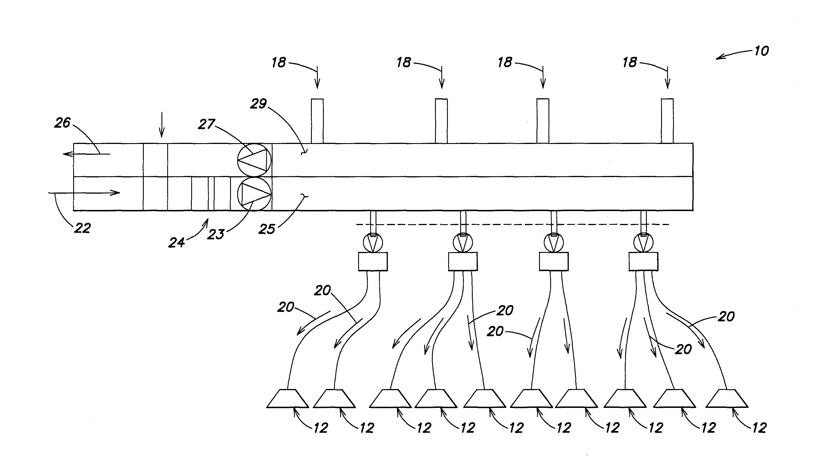
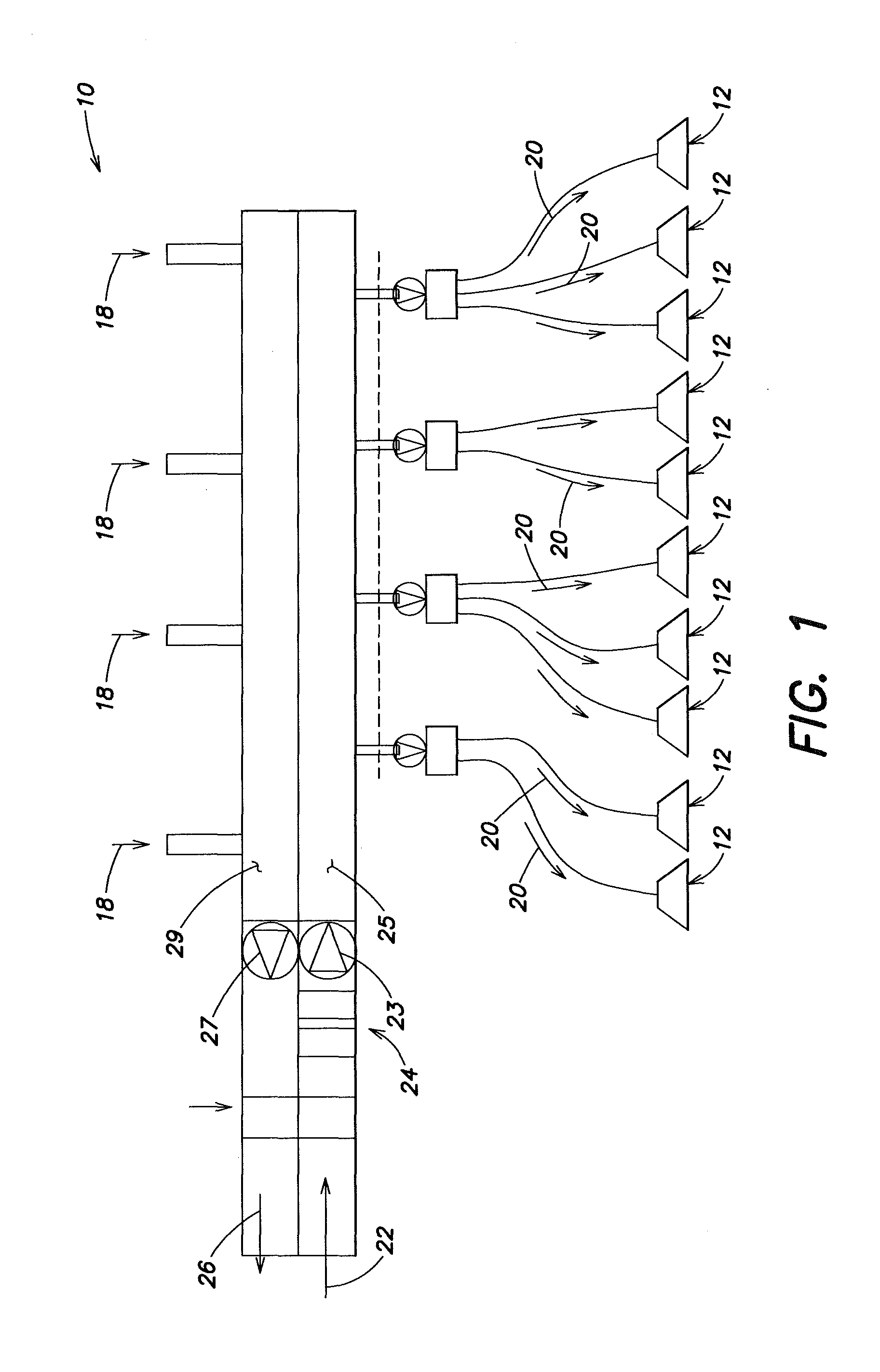
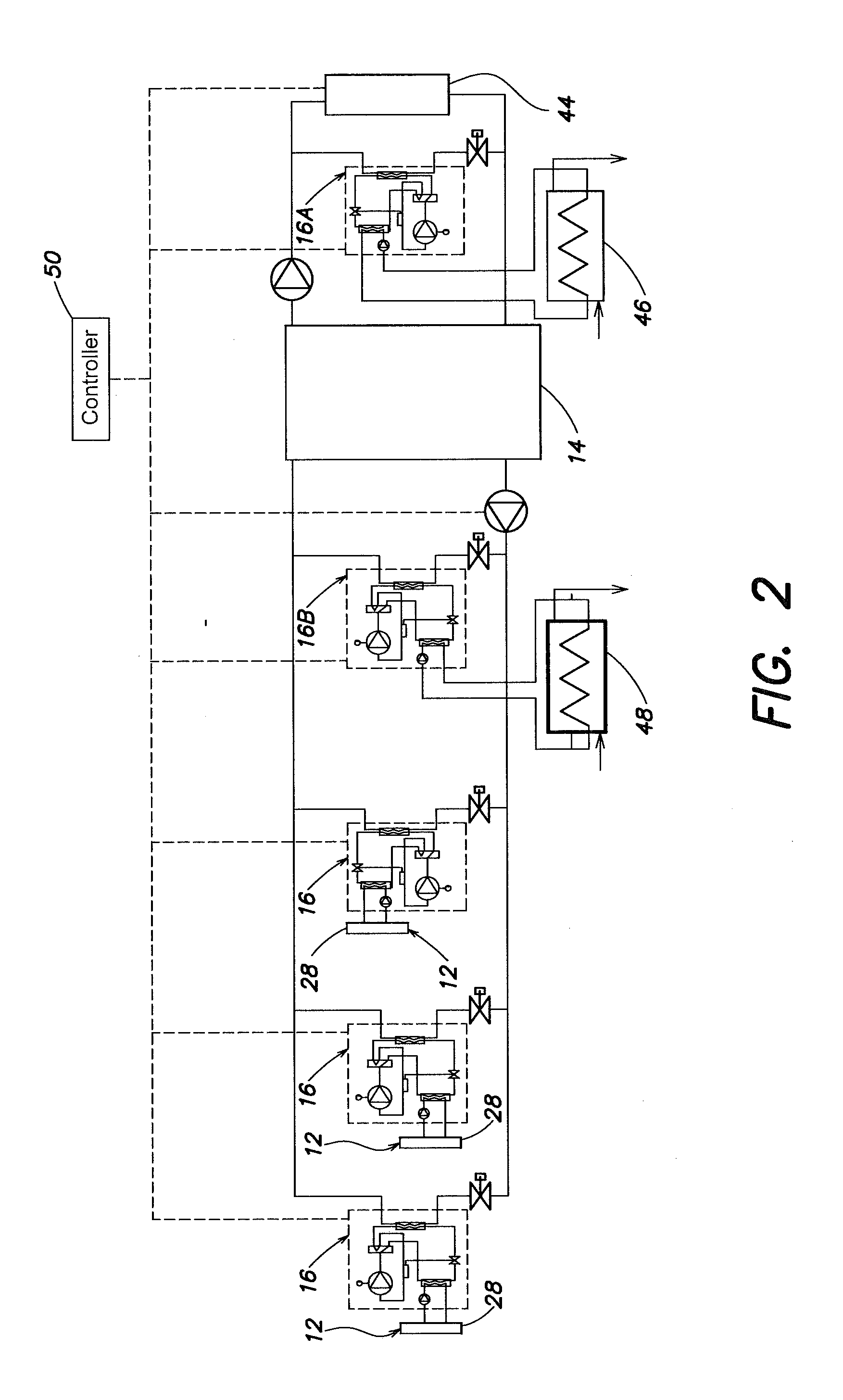
[0015]Referring to FIGS. 1 and 2, the present system for conditioning air within an air handling system 10 of a building includes one or more heating-cooling units 12 connected to the air handling system 10, a primary storage device 14, and one or more heat pumps 16 connected to the primary water storage device 14 and the heating-cooling unit 12. The air handling system 10 can be operated (e.g., in cooling mode) in a such way that air entering the building is dry enough to allow a chilled beam or fan coil unit to operate without moisture condensation. In other words, the air handling system is taking care of the latent load of the air while the chilled beam or fan coil unit is addressing the sensible heat of the air.

[0016]Referring to FIG. 1, the air handling system 10 is operable to cycle air through the building. Air is returned from the building (“return air”18) and into the engagement with the heating-cooling unit 12. Air conditioned by a heating-cooling unit 12 is supplied to t...


PUM


Abstract

A system and method for conditioning air within an air handling system of a building is provided. The building has a hot water source and a cold water source. The conditioning system includes at least one heating-cooling unit connected to the air handling system, a primary water storage device, at least one heat pump, and a controller. The heating-cooling unit, which includes at least one chilled beam, is operable to transfer heat into or out of air passing within the air handling system of the building. The primary water storage device is operable to store a volume of water within a predetermined temperature range. The primary water storage device is in communication with the hot water source and the cold water source. The heat pump is connected to the primary water storage device and the chilled beam. The controller is adapted to selectively drive the heat pump to transfer heat between the primary water storage device and the chilled beam. The controller is also adapted to selectively control the system to transfer heat into or out of the primary water storage device to maintain the water within the primary storage device within the predetermined temperature range.

Description

[0001]Applicant hereby claims priority benefits under 35 U.S.C. §119(e) of U.S. Provisional Patent Application No. 61 / 246,806 filed Sep. 29, 2009, the disclosure of which is herein incorporated by reference.BACKGROUND OF THE INVENTION[0002]1. Technical Field[0003]The present method and system relate to methods and systems for maintaining air temperature within a building in general, and to methods and systems for maintaining air temperature within an air handling system of a building in particular.[0004]2. Background Information[0005]In large buildings, traditional air conditioning systems are often centralized. Most centralized air conditioning systems require space for machinery rooms (usually in a basement), which rooms typically include installed chillers. Thermal energy residing within the building is transferred to the outside of the building via cooling towers located outside of the building. Alternatively, air cooled chillers may be installed outside of the building. Fresh a...

Claims


Application Information

Patent Timeline
IPC IPC(8): G05D23/00
CPCF24D5/04F24D5/12F24D19/1087F24F3/08F25B2400/24F24H4/04F24H6/00F25B29/003F25B2400/06F24F2203/02Y02B30/13Y02B30/12F24H15/38F24H15/375F25B13/00F25B49/02
Inventor GRABON, MICHELYUAN, SHUIKUANG, YUHUILUO, DONGOGGIANU, STELLA M.
Owner CARRIER CORP
Why Eureka
Try Eureka