Method of controlling a cooling device for a machine tool

a cooling device and machine tool technology, applied in the direction of process and machine control, manufacturing tools, instruments, etc., can solve the problems of continuing to stop the stoppage of the machine tool, achieve the effect of improving cutting conditions, reducing stoppage time, and improving tool li

Active Publication Date: 2012-09-27
SAFRAN LANDING SYSTEMS
View PDF4 Cites 18 Cited by
  • Summary
  • Abstract
  • Description
  • Claims
  • Application Information

AI Technical Summary

Benefits of technology

[0005]An object of the invention is to provide a solution that enables machine tool stopp...

Problems solved by technology

In spite of such a cooling device being used, machine tools continue to be s...

Method used


Image

  • Method of controlling a cooling device for a machine tool
  • Method of controlling a cooling device for a machine tool
  • Method of controlling a cooling device for a machine tool

Examples


Embodiment Construction

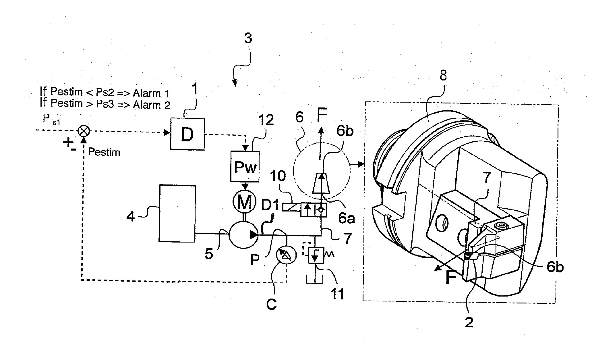
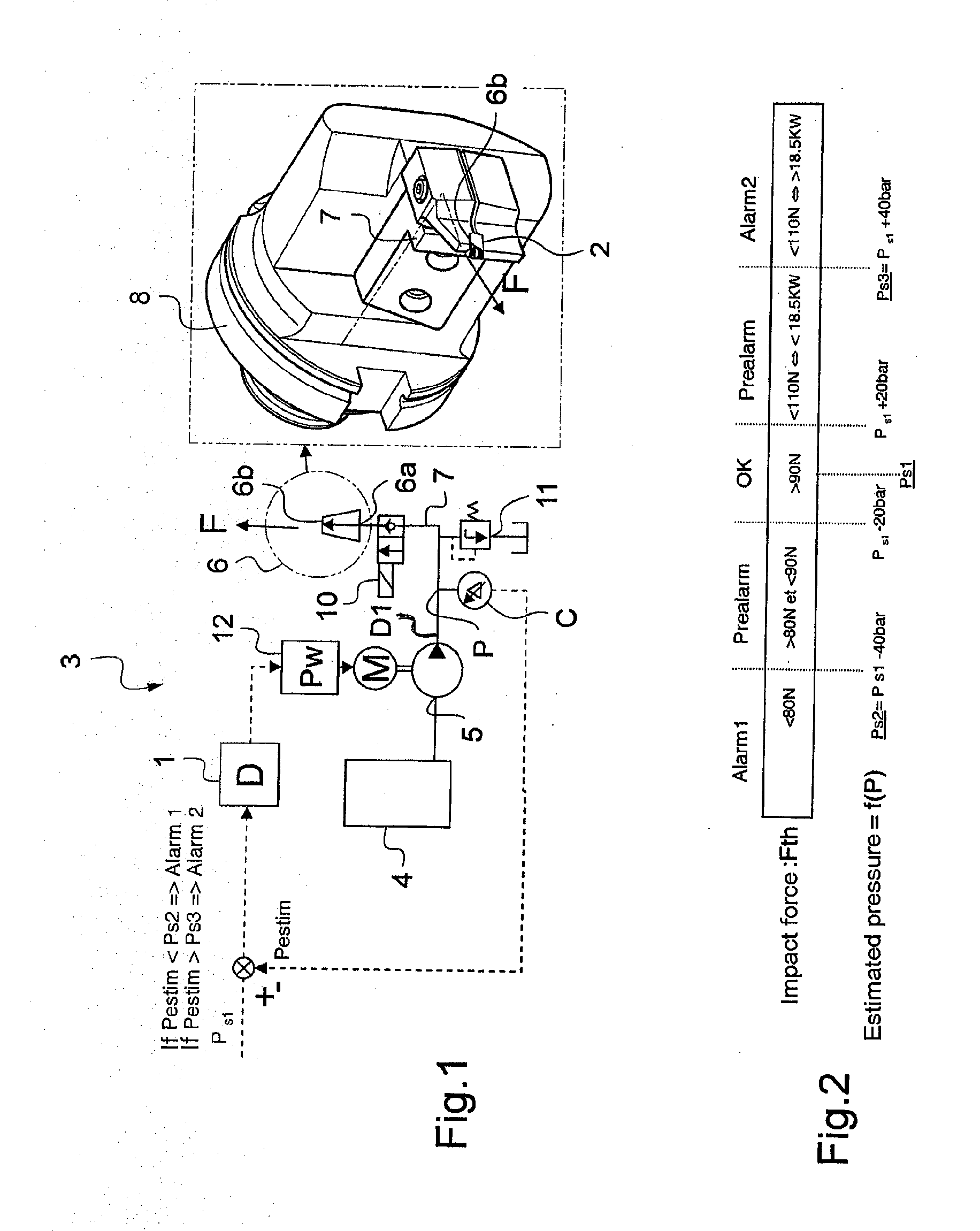
[0029]FIG. 1 shows a machine tool 3 having a cutting tool 2 and a cooling device 1 for implementing the method of the invention.

[0030]The cooling device 1 has a cooling nozzle 6 shown in detail in the box in FIG. 1.

[0031]The nozzle is assembled on a tool carrier 8 of the machine tool 3 and it includes actuators for moving the tool and the tool carrier in compliance with programmed commands. The tool 2, specifically a machining tip for performing a turning operation, is fastened on the tool carrier 8. The outlet 6b from the nozzle is directed towards a portion of the cutting tool 2 so as to cool its cutting face directly.

[0032]The nozzle 6 is fed by a fluid transfer duct 7 that extends at least in part inside the tool carrier 8, with this portion being represented by a chain-dotted line.

[0033]The tool carrier 8 comprises a perforated metal block, the perforation forming a portion of the fluid transfer duct 7, and the nozzle 6 is assembled with the metal block so that its nozzle inlet...


PUM


Abstract

A method of controlling a cooling device for cooling a cutting tool in a machine tool. The method comprising the steps of:
    • controlling the motor to drive the pump in such a manner that the pump feeds the nozzle with machining fluid at a constant flow rate D1 that is equal to a first flow rate setpoint;
    • measuring a parameter P representative of a fluid outlet pressure from the nozzle; and
    • comparing an estimated outlet pressure Pestim as estimated from the parameter P with a first predetermined pressure threshold Ps1, and controlling the motor so as to increase the fluid flow rate D1 as delivered by the pump if the estimated output pressure drops below the first pressure threshold Ps1.

Description

BACKGROUND OF THE INVENTION[0001]The invention relates to the field of cooling a cutting tool in a machine tool that has such a cutting tool.[0002]In machine tools, it is common practice to use cooling devices to spray and lubricate cutting tools, thereby limiting tool wear and reducing the risk of breakage and of the machine tool being stopped.[0003]By delivering a stream of machining fluid into the region where the tool comes into contact with the part being machined, it is possible to reduce friction and to cause the heat that is produced to be dissipated in the stream of cooling fluid.[0004]In spite of such a cooling device being used, machine tools continue to be stopped as a result of wear, of a tool breaking, or of becoming clogged with swarf.OBJECT OF THE INVENTION[0005]An object of the invention is to provide a solution that enables machine tool stoppage time to be reduced, that improves cutting conditions, and that also improves tool lifetimes.SUMMARY OF THE INVENTION[0006...

Claims


Application Information

Patent Timeline
IPC IPC(8): G05D7/00
CPCB23Q11/10B23Q17/00B23Q11/1084B23Q11/1038
Inventor CLAUSMANN, DENISAUGELMANN, LAURENTKEHREN, CLAUDEJOUBERT, CHRISTOPHE
Owner SAFRAN LANDING SYSTEMS
Why Eureka
Try Eureka