Hermetically sealed container, image display apparatus, and their manufacturing methods

a technology of image display apparatus and hermetically sealed containers, applied in the direction of cabinets/cabinets/drawer details, furniture parts, cabinets, etc., can solve the problems of glass frit damage, and insufficient reliability of hermetically sealed containers, so as to improve reliability, easy maintenance, and improve bonding force

Inactive Publication Date: 2012-10-04
CANON KK
View PDF2 Cites 58 Cited by
  • Summary
  • Abstract
  • Description
  • Claims
  • Application Information

AI Technical Summary

Benefits of technology

[0011]In the hermetic container of the invention, the container is in a state where at least one of the first and second substrates is elastically deformed and a compressing force acts continuously in the height direction of the first bonding member. Therefore, even if temperature distribution occurred in the hermetic container, the tractive force is difficult to act in the height direction of the first bonding member, even if glass frit is used as a first bonding member, the hermetic sealing can be easily maintained, and its reliability is improved. Since the first and second substrates are bonded not only by the first bonding member but also by the second bonding me

Problems solved by technology

On the other hand, in many cases, a temperature change of the hermetic container does not uniformly occur as a whole.
Therefore, if the tractive force in the height direction acts on the glass frit as mentioned above, the glass frit is damaged and hermetic sealing is liable to be lost.
There is, however, such a problem that a reliability about t

Method used


Image

  • Hermetically sealed container, image display apparatus, and their manufacturing methods
  • Hermetically sealed container, image display apparatus, and their manufacturing methods
  • Hermetically sealed container, image display apparatus, and their manufacturing methods

Examples


example 1

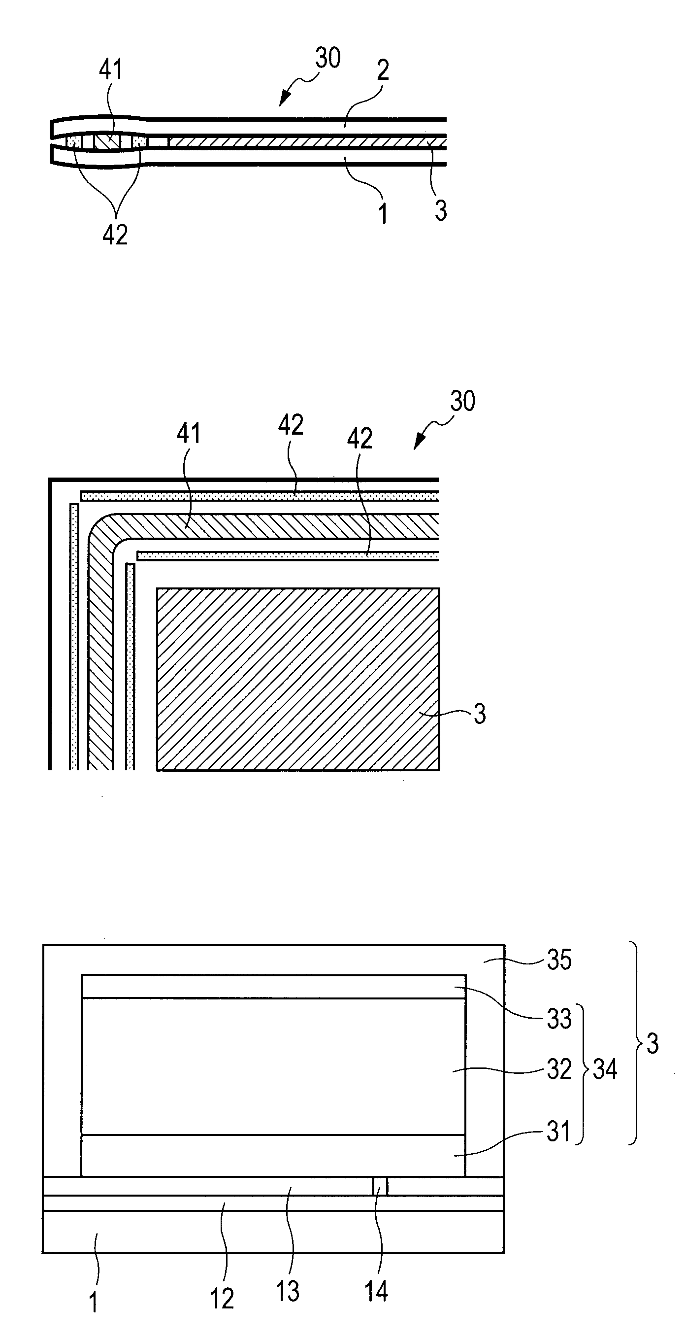
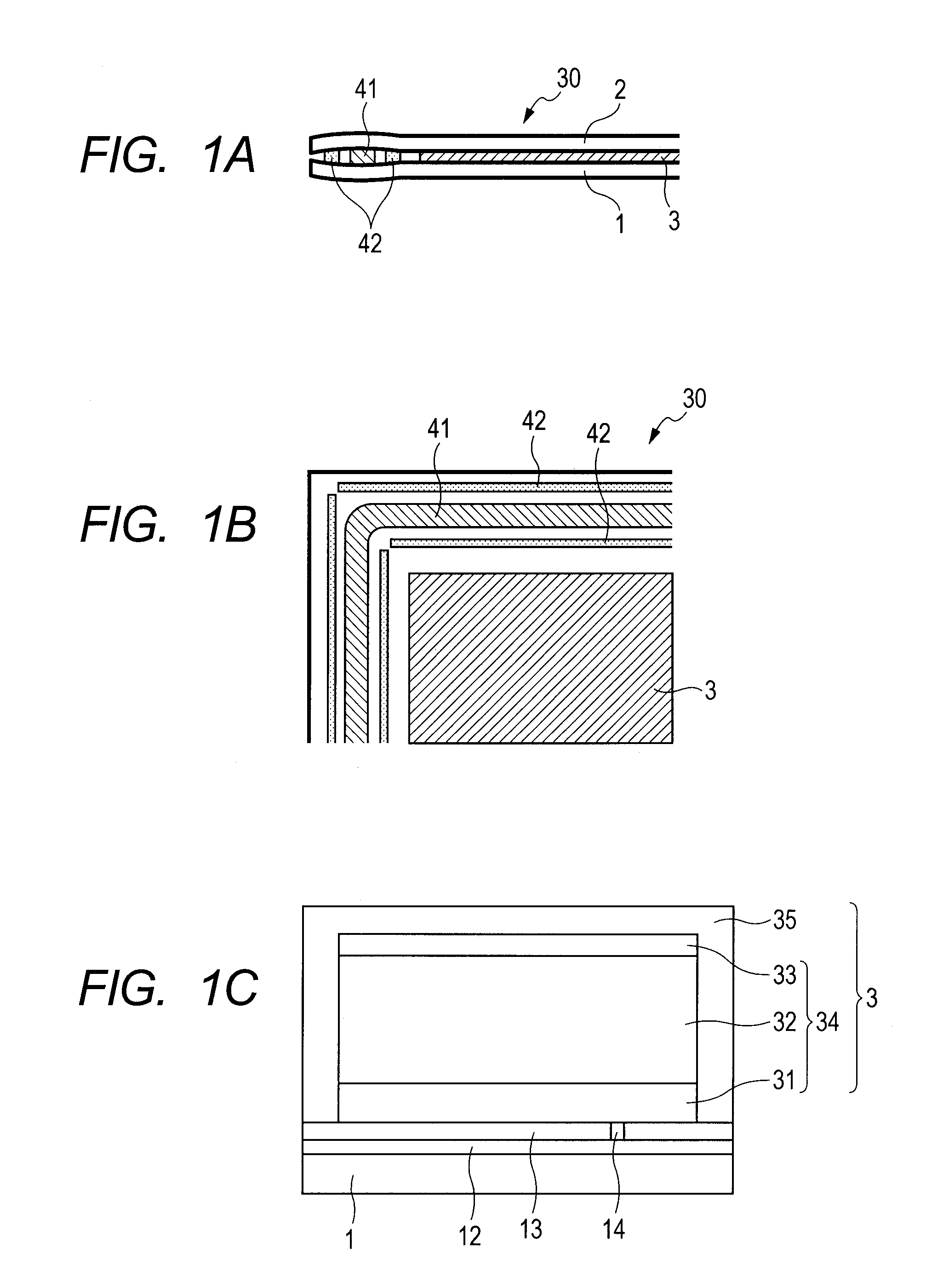
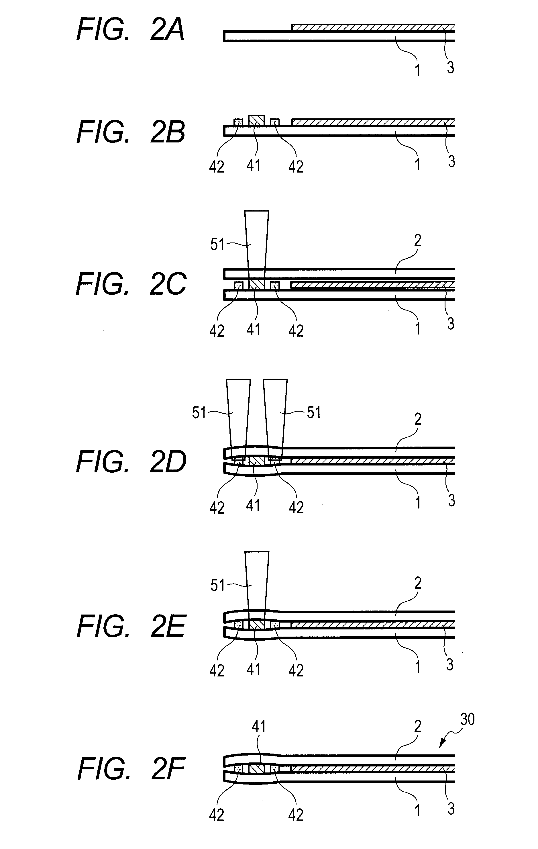
[0051]In this Example, the hermetic container 30 which has been described in FIGS. 1A to 1C and constructs the envelope of the OLED is manufactured by the procedure of FIGS. 2A to 2F. While describing the manufacturing method of the hermetic container 30, the structure of the hermetic container 30 will be also described hereinbelow.

[0052]First, the first substrate 1 and the second substrate 2 are prepared as illustrated in FIGS. 1A to 1C and 2A. The first substrate 1 is a glass plate having a thickness of 0.5 mm. The TFT circuit 12, planarized film 13, and contact hole 14 are provided on the first substrate 1. The lower electrode 31, organic EL layer 32, upper electrode 33, and protective layer 35 which construct the light emitting portion 3 are further provided on the planarized film 13.

[0053]Subsequently, as illustrated in FIG. 2B, the first bonding member 41 is screen printed in an annular shape so as to surround the light emitting portion 3. The second bonding members 42 are res...

example 2

[0063]Example 2 will be described with reference to FIGS. 3A to 3F. In a manner similar to the Example 1, the first substrate 1 and the second substrate 2 are prepared and the first bonding member 41 and the second bonding members 42 are placed. At this time, the second bonding members 42 are formed so as to have a height similar to that of the first bonding member 41.

[0064]Subsequently, as illustrated in FIGS. 3C and 3D, the local heating light 51 is irradiated to the second bonding members 42, thereby bonding the first and second substrates 1 and 2. At this time, a pressure is applied to the second bonding members 42 through the first and second substrates 1 and 2. The second bonding members 42 are thinner than the first bonding member 41 by the local heating light 51 and the pressure.

[0065]Subsequently, as illustrated in FIG. 3E, by irradiating the local heating light 51 to the first bonding member 41, the first substrate 1 and the second substrate 2 are bonded. Since the first b...

example 3

[0067]Example 3 will be described with reference to FIGS. 4A to 5F.

[0068]In a manner similar to the Example 1, the first substrate 1 and the second substrate 2 are prepared.

[0069]Subsequently, the second bonding members 42 are placed inside of the first bonding member 41 placed in the annular shape. The first bonding member 41 and the second bonding members 42 are formed from the glass frit in a manner similar to the Example 1 and are formed by the screen printing. The second bonding members 42 are placed in a continuous dotted shape in parallel with the first bonding member 41.

[0070]The first bonding member 41 is bonded by using the local heating light 51 in a manner similar to the Example 1. After that, the first substrate 1 and the second substrate 2 are bent so as to sandwich the second bonding members 42 with a pressure, thereby bonding the first and second substrates 1 and 2 by using the local heating light 51.

[0071]Further, as illustrated in FIG. 5E, the first bonding member ...


PUM

PropertyMeasurementUnit
Forceaaaaaaaaaa
Heightaaaaaaaaaa

Abstract

A hermetic container comprises first and second substrates and bonded by bonding members to form a hermetically sealed space therebetween. Second bonding members placed on both sides of a first bonding member to form the hermetically sealed space between the substrates are sandwiched between the substrates, thereby bonding the substrates together with the first bonding member. A height of first bonding member is higher than that of second bonding member and at least one of the substrates is elastically deformed and is bonded by the first bonding member and the second bonding members. Thus, the hermetic container in which a compressing force has been applied to a height direction of the first bonding member is obtained.

Description

BACKGROUND OF THE INVENTION[0001]1. Field of the Invention[0002]The present invention relates to a hermetically sealed container (hereinbelow, referred to as a hermetic container) in which a first substrate and a second substrate which are placed in opposition to each other to firm a gap therebetween are bonded by a bonding member which is sandwiched between both of those substrates, is placed so as to surround the gap, and forms a hermetically sealed space inside of the substrates, and also relates to an image display apparatus using the hermetic container as an envelope and to manufacturing methods of the hermetic container and the image display apparatus.[0003]2. Description of the Related Art[0004]In the related art, image display apparatuses of a flat panel type such as organic LED display (OLED), field emission display (FED), plasma display panel (PDP), and the like have been known. Each of those image display apparatuses has an envelope which is manufactured by hermetically b...

Claims


Application Information

Patent Timeline
IPC IPC(8): H05K5/02H05K13/00
CPCH01L51/5246C03C27/06H10K50/8426
Inventor NIIBORI, KENJI
Owner CANON KK
Why Eureka
Try Eureka