
Wireless communications device including side-by-side passive loop antennas and related methods

a passive loop antenna and wireless communication technology, applied in the field of communication, can solve the problems of reducing the bandwidth of envelopes, rarely approaching the chu's limit bandwidth, and providing only quadratic, and achieves the effects of reducing size, increasing gain, and maintaining performan

Active Publication Date: 2012-10-04
HARRIS CORP
View PDF9 Cites 114 Cited by
  • Summary
  • Abstract
  • Description
  • Claims
  • Application Information

AI Technical Summary

Benefits of technology

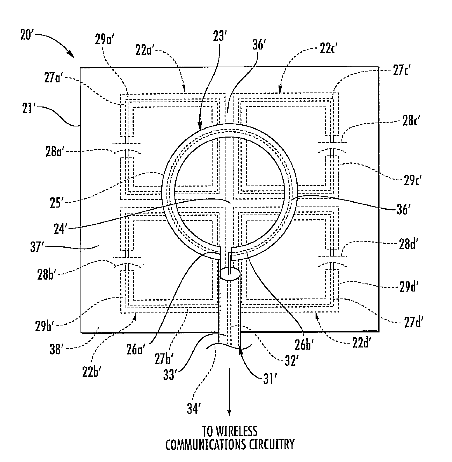
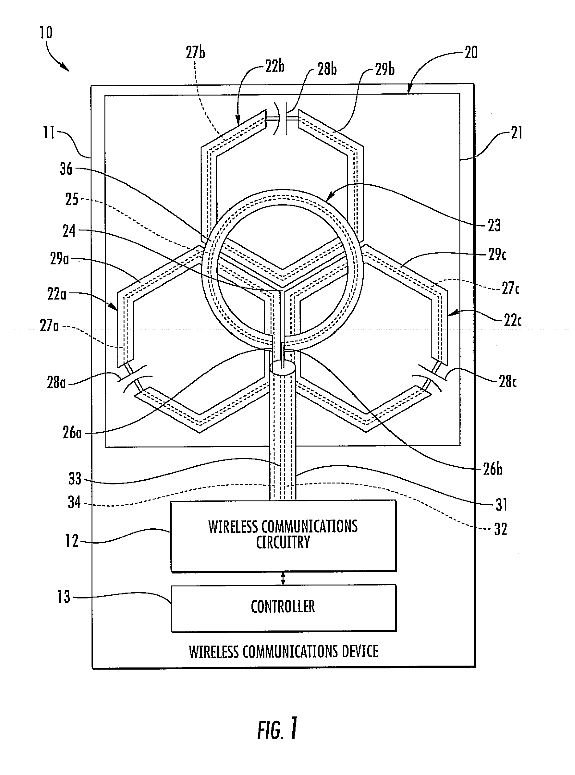
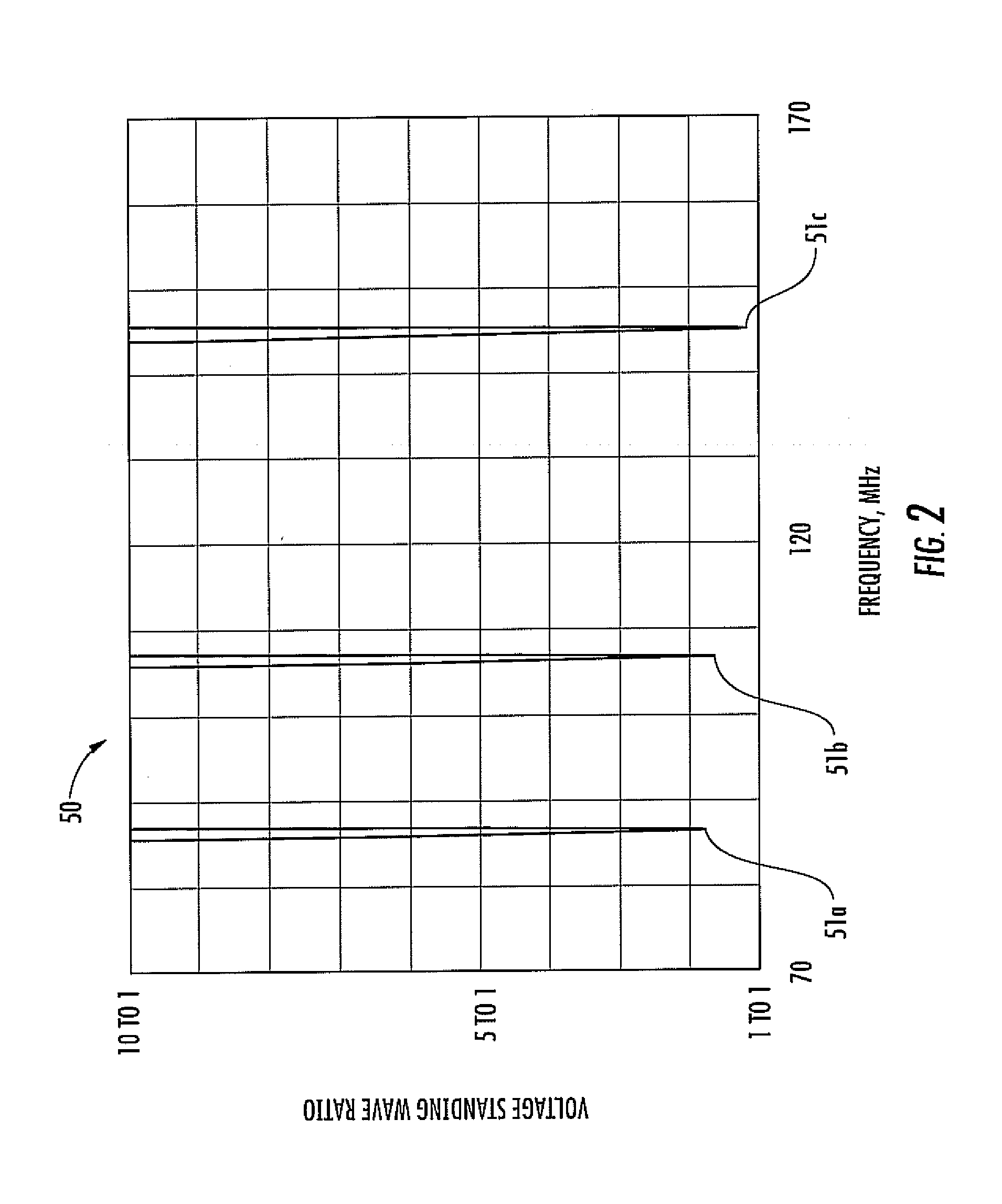
[0015]The antenna assembly also includes an active loop antenna carried by the substrate and arranged to be at least partially coextensive with each of the plurality of passive loop antennas. The active loop antenna includes an active loop conductor and a pair of feedpoints defined therein, for example. Accordingly, the antenna assembly has a relatively reduced size, while maintaining performance, for example, by providing multi-band frequency operation, and providing increased gain with respect to area.

Problems solved by technology

One challenge this poses for wireless device manufacturers is designing antennas that provide desired operating characteristics within the relatively limited amount of space available for antennas.
Unfortunately, antennas, and in particular, broadband antennas, have not been reduced in size at a comparable level and often are one of the larger components used in a smaller communications device.
Unfortunately, such an antenna fitting inside a radius=λ / 20 spherical envelope may not have more than 6.1% of this bandwidth.
Further, practical antennas seldom approach the Chu's limit bandwidth.
At electrically small size, however, (r>λ / 2π), the spiral may provide only a quadratic, bandpass type response with greatly limited bandwidth.
However, none of these approaches are focused on providing an antenna with multi-band frequency operation, while being small in size, and having desired gain for area.

Method used


Image

  • Wireless communications device including side-by-side passive loop antennas and related methods
  • Wireless communications device including side-by-side passive loop antennas and related methods
  • Wireless communications device including side-by-side passive loop antennas and related methods

Examples


Embodiment Construction

[0029]The present invention will now be described more fully hereinafter with reference to the accompanying drawings, in which preferred embodiments of the invention are shown. This invention may, however, be embodied in many different forms and should not be construed as limited to the embodiments set forth herein. Rather, these embodiments are provided so that this disclosure will be thorough and complete, and will fully convey the scope of the invention to those skilled in the art. Like numbers refer to like elements throughout, and prime and multiple notation are used to indicate similar elements in alternative embodiments.

[0030]Referring initially to FIG. 1, a wireless communications device 10 includes a housing 11 and wireless communications circuitry 12 carried by the housing. The wireless communications circuitry 12 may be cellular communications circuitry or radiolocation tag circuitry, for example, and be configured to communicate voice and / or data. The wireless circuitry ...


PUM

PropertyMeasurementUnit
Fractionaaaaaaaaaa
Lengthaaaaaaaaaa
Lengthaaaaaaaaaa

Abstract

A wireless communications device may include a housing, and wireless communications circuitry carried by the housing. The wireless communications device may also include an antenna assembly carried by the housing and coupled to the wireless communications circuitry. The antenna assembly may include a substrate and a plurality of passive loop antennas carried by the substrate and arranged in side-by-side relation. Each of the plurality of spaced apart passive loop antennas may include a passive loop conductor and a tuning element coupled thereto. The antenna assembly may also include an active loop antenna carried by the substrate and arranged to be at least partially coextensive with each of the plurality of passive loop antennas. The active loop antenna may include an active loop conductor and a pair of feedpoints defined therein.

Description

FIELD OF THE INVENTION[0001]The present invention relates to the field of communications, and, more particularly, to antennas and related methods.BACKGROUND OF THE INVENTION[0002]Antennas may be used for a variety of purposes, such as communications or navigation, and portable radio devices may include broadcast receivers, pagers, or radio location devices (“ID tags”). The cellular telephone is an example of a wireless communications device, which is nearly ubiquitous. A relatively small size, increased efficiency, and a relatively broad radiation pattern are generally desired characteristics of an antenna for a portable radio or wireless device. Additionally, as the functionality of a wireless device continues to increase, so too does the demand for a smaller wireless device which is easier and more convenient for users to carry. One challenge this poses for wireless device manufacturers is designing antennas that provide desired operating characteristics within the relatively limi...

Claims


Application Information

Patent Timeline
IPC IPC(8): H01Q7/00H01P11/00
CPCH01Q1/243H01Q7/00H01Q5/385H01Q5/0065Y10T29/49016H01Q21/061H01Q1/24H01Q21/06
Inventor PARSCHE, FRANCIS EUGENE
Owner HARRIS CORP
Learn More