
Liquid crystal display device, alignment film, and methods for manufacturing the same

a technology of liquid crystal display and alignment film, which is applied in the direction of optics, instruments, transportation and packaging, etc., can solve the problems of reducing the display quality of the liquid crystal display devi

Active Publication Date: 2012-10-04
SHENZHEN CHINA STAR OPTOELECTRONICS TECH CO LTD
View PDF7 Cites 128 Cited by
  • Summary
  • Abstract
  • Description
  • Claims
  • Application Information

AI Technical Summary

Benefits of technology

[0011]Each of the first and second pre-tilting functional groups may comprise one or more of

Problems solved by technology

In the hardening process, the non-hardened reactive mesogen may remain in the liquid crystal layer, increasing the persistence defect of the liquid crystal display device and thus reducing the display quality of the liquid crystal display device.

Method used


Image

  • Liquid crystal display device, alignment film, and methods for manufacturing the same
  • Liquid crystal display device, alignment film, and methods for manufacturing the same
  • Liquid crystal display device, alignment film, and methods for manufacturing the same

Examples


Embodiment Construction

[0065]Exemplary embodiments of the present invention will now be described in detail with reference to the accompanying drawings. The present invention may, however, be embodied in many different forms and should not be construed as being limited to the embodiments set forth herein.

[0066]Throughout the following description and drawings, the same reference numerals may refer to the same components, features and / or structures.

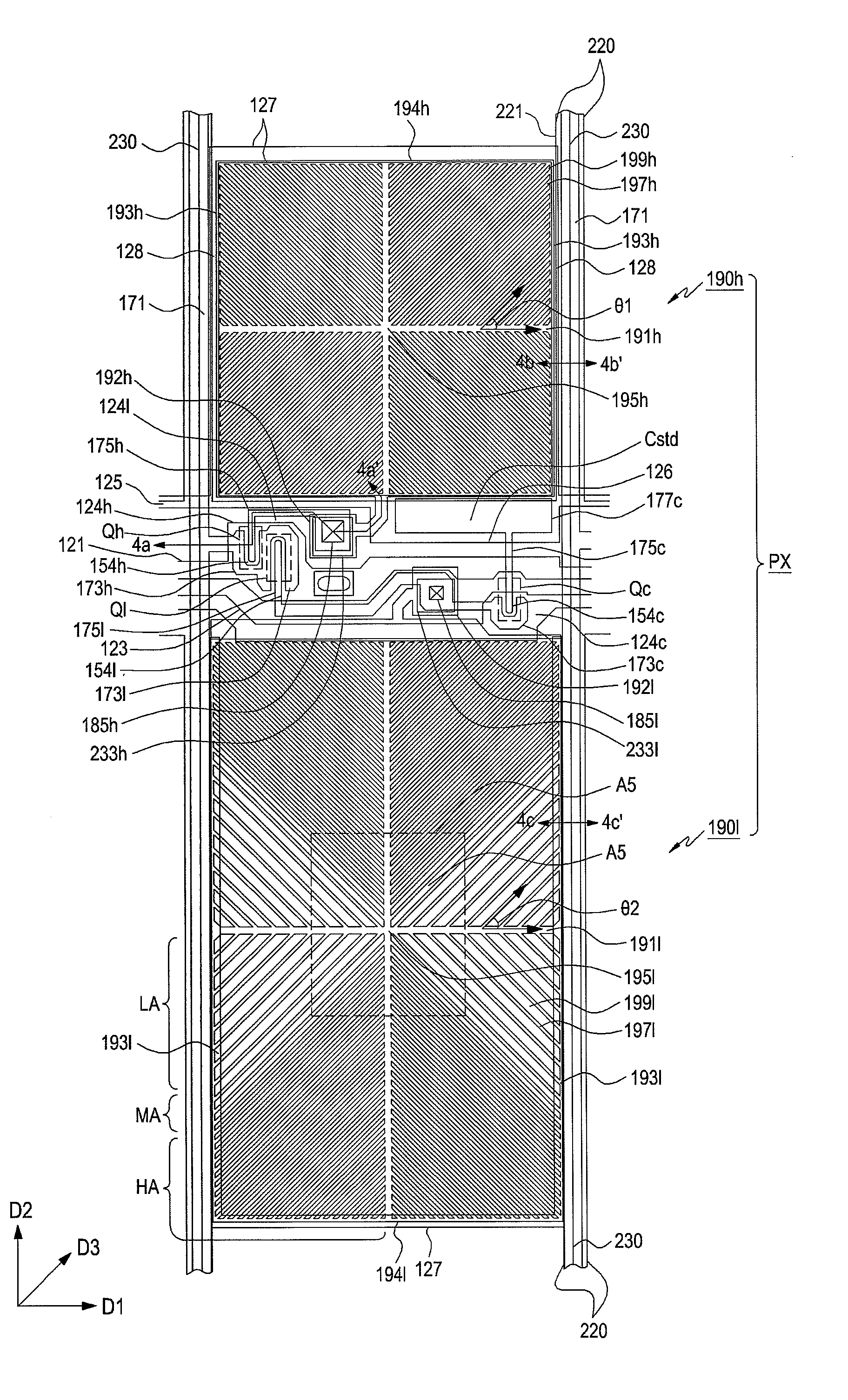
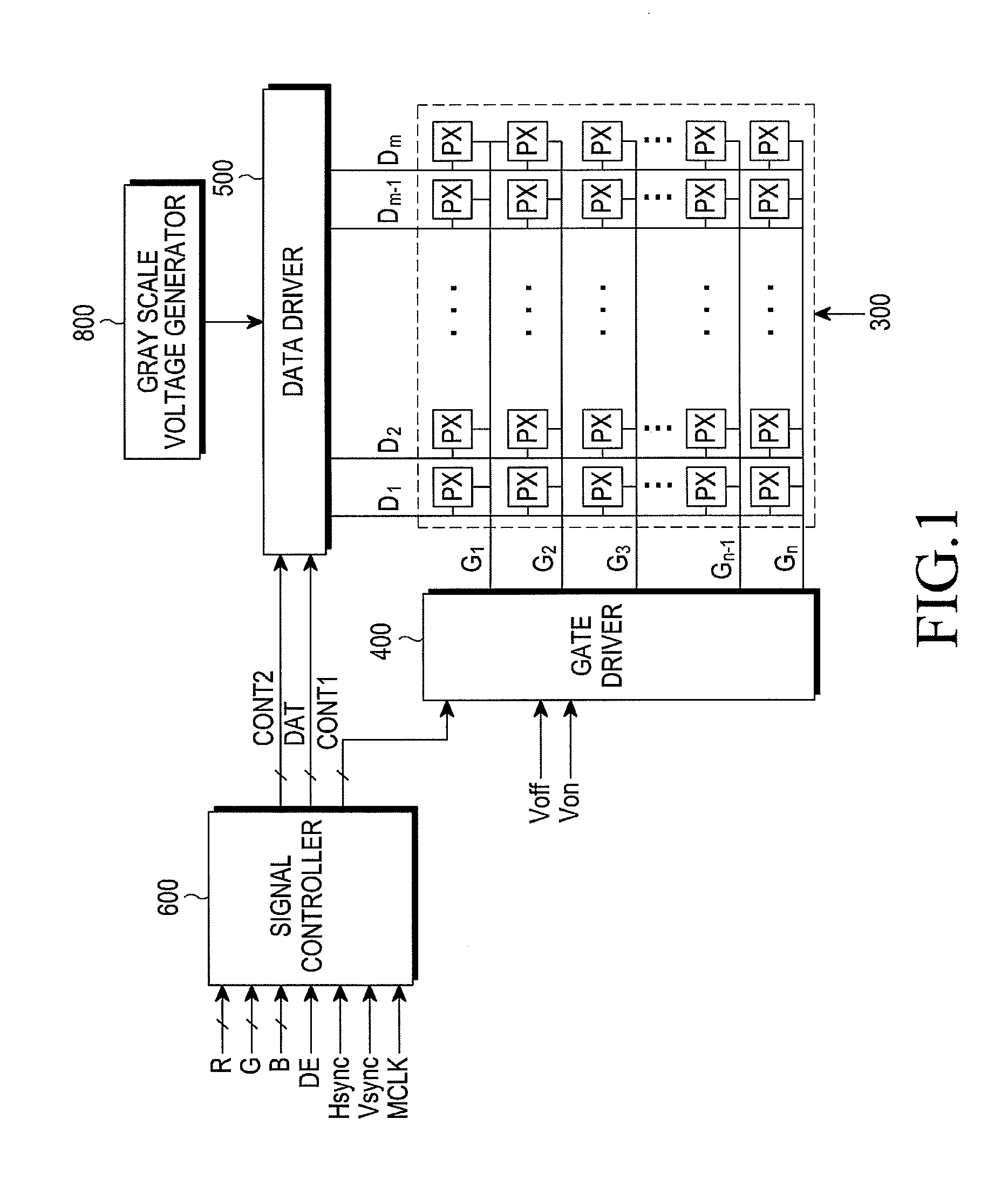
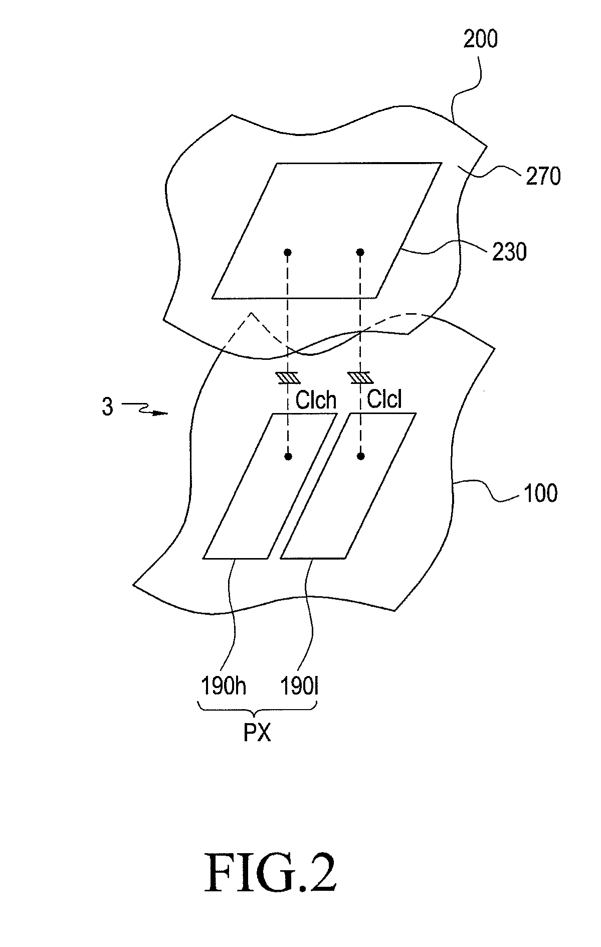
[0067]A liquid crystal display device according to an exemplary embodiment of the present invention will be described in detail with reference to FIGS. 1 and 2. FIG. 1 is a block diagram of a liquid crystal display device according to an exemplary embodiment of the present invention. FIG. 2 schematically illustrates a structure of two subpixels 190h and 190l constituting one pixel PX in a liquid crystal display device according to an exemplary embodiment of the present invention. As illustrated in FIG. 1, a liquid crystal display device includes a liquid crystal...


PUM

PropertyMeasurementUnit
Phase separationaaaaaaaaaa
Structureaaaaaaaaaa
Ratioaaaaaaaaaa

Abstract

A liquid crystal display device is provided, including a liquid crystal layer interposed between a first display panel and a second display panel; and an alignment film formed on at least one of the first and second display panels, the alignment film including first polysiloxanes and second polysiloxanes disposed on the first polysiloxanes, wherein a first portion of silicon atoms of the second polysiloxanes are bonded to vertical functional groups interacting with liquid crystal molecules in the liquid crystal layer, and to first pre-tilting functional groups aligning the liquid crystal molecules in the liquid crystal layer to be tilted with respect to at least one of the first and second display panels by being cross-linked. The bonding structure of the first and the second polysiloxanes being different.

Description

CROSS-REFERENCE TO RELATED APPLICATIONS[0001]This application claims priority under 35 U.S.C. §119(a) to Korean Patent Application filed in the Korean Intellectual Property Office on May 2, 2011 and assigned Serial No. 10-2011-0041685 and Korean Patent Application filed in the Korean Intellectual Property Office on Aug. 30, 2011 and assigned Serial No. 10-2011-0087424, and is a continuation-in-part of U.S. Ser. No. 13 / 018,630 filed Feb. 1, 2011 and U.S. Ser. No. 13 / 018,872 also filed Feb. 1, 2011, each of the foregoing U.S. applications claim priority under 35 U.S.C. §119(a) to Korean Patent Application filed in the Korean Intellectual Property Office on Apr. 2, 2010 and assigned Serial No. 10-2010-0030591, Korean Patent Application filed in the Korean Intellectual Property Office on May 20, 2010 and assigned Serial No. 10-2010-0047746, Korean Patent Application filed in the Korean Intellectual Property Office on Jun. 4, 2010 and assigned Serial No. 10-2010-0052878, Korean Patent Ap...

Claims


Application Information

Patent Timeline
IPC IPC(8): G02F1/1337
CPCG02F1/133707G02F1/133723G02F1/133753G02F1/133788G02F1/134309Y10T428/1014G02F2001/133531G02F2001/133742G02F2001/133746C08G77/20G02F1/1337G02F1/1393C09K2323/023G02F1/133531G02F1/133746G02F1/133742
Inventor CHOI, KYONG-SIKPARK, MYUNG-JAEPARK, MIN-WOOKKIM, SUNG-HOONLEE, GAK-SEOKSHIN, WOO-JUNGLEE, JUN-HYUPOH, KEUN-CHANKIM, SANG-GYUNKIM, SU-JEONGPARK, SEUNG-BEOMJEONG, YOUN-HAK
Owner SHENZHEN CHINA STAR OPTOELECTRONICS TECH CO LTD
Learn More