Exhaust emission control device

a technology of exhaust emission control and control device, which is applied in the direction of machines/engines, mechanical equipment, separation processes, etc., can solve the problems of affecting the mountability of vehicles, achieve the effect of enhancing nox emission control performance, and facilitating the flow of urea water

Active Publication Date: 2012-10-11
HINO MOTORS LTD +1
View PDF5 Cites 15 Cited by
  • Summary
  • Abstract
  • Description
  • Claims
  • Application Information

AI Technical Summary

Benefits of technology

[0021]According to the exhaust emission control device of the invention described above, various excellent effects can be exhibited as described below.
[0022](I) According to the invention claimed in claim 1, even if the added amount of the urea water is increased so as to enhance NOx emission control performance and thus the urea water not gasified forms a flow running on the inner periphery of the mixing pipe along the swirling flow of the exhaust gas, the urea water can be prevented from running from the opening sections at the entry end of the mixing pipe down toward the upstream side and therefore, all of the urea water added by the urea water adding means can be guided as ammonia to the selective reduction catalyst to maintain well the NOx emission control performance and the added amount control of the urea water and to prevent occurrence of corrosion attributable to the urea water flowing down toward the upstream side.
[0023](II) According to the invention claimed in claim 2, the inflow angle of the exhaust gas having passed through the particulate filter to the opening sections is made small so that a vector of the flow of the exhaust gas when running to the opening sections can be directed toward the exit end of the mixing pipe. As a result, vectors of the swirling flow and of the flow of the urea water along the swirling flow can be directed more strongly toward the exit end of the mixing pipe, leading to facilitated running of the flow of the urea water over the opening sections and further reliable prevention of the urea water from flowing from the opening sections down toward the upstream side.
[0024](III) According to the invention claimed in claim 2, the angle made by the inflow direction of the exhaust gas to the opening sections and the spraying direction of the urea water adding means can be made shallow to lessen the effect of the flow of the exhaust gas on the spraying of the urea water, which can prevent the spray from the urea water adding means from being fanned by the exhaust gas flow into direct hit and lingering-around of the urea water on and at the stagnant areas off the flow of the exhaust gas and a resultant partial corrosion.

Problems solved by technology

There is, however, a problem that the spaced-apart arrangement of the particulate filter and the selective reduction catalyst with a sufficient distance in between would significantly impair a mountability on a vehicle.

Method used


Image

  • Exhaust emission control device
  • Exhaust emission control device
  • Exhaust emission control device

Examples


Embodiment Construction

[0032]Embodiments of the invention will be described with reference to the drawings.

[0033]FIGS. 4 and 5 show an embodiment of the invention in which parts similar to those in FIGS. 1-3 are represented by same reference numerals.

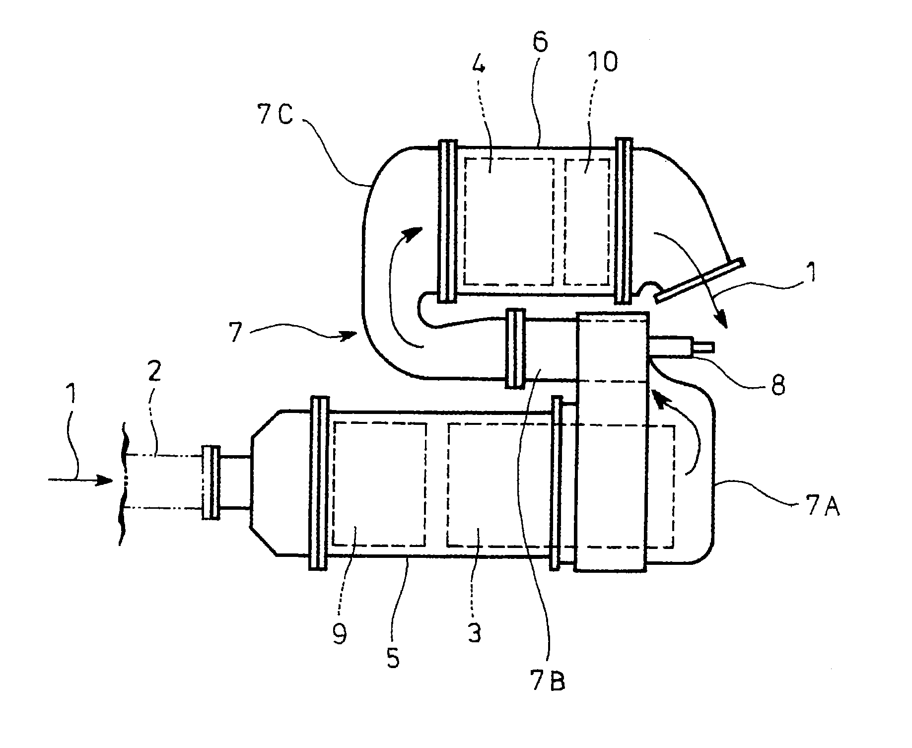
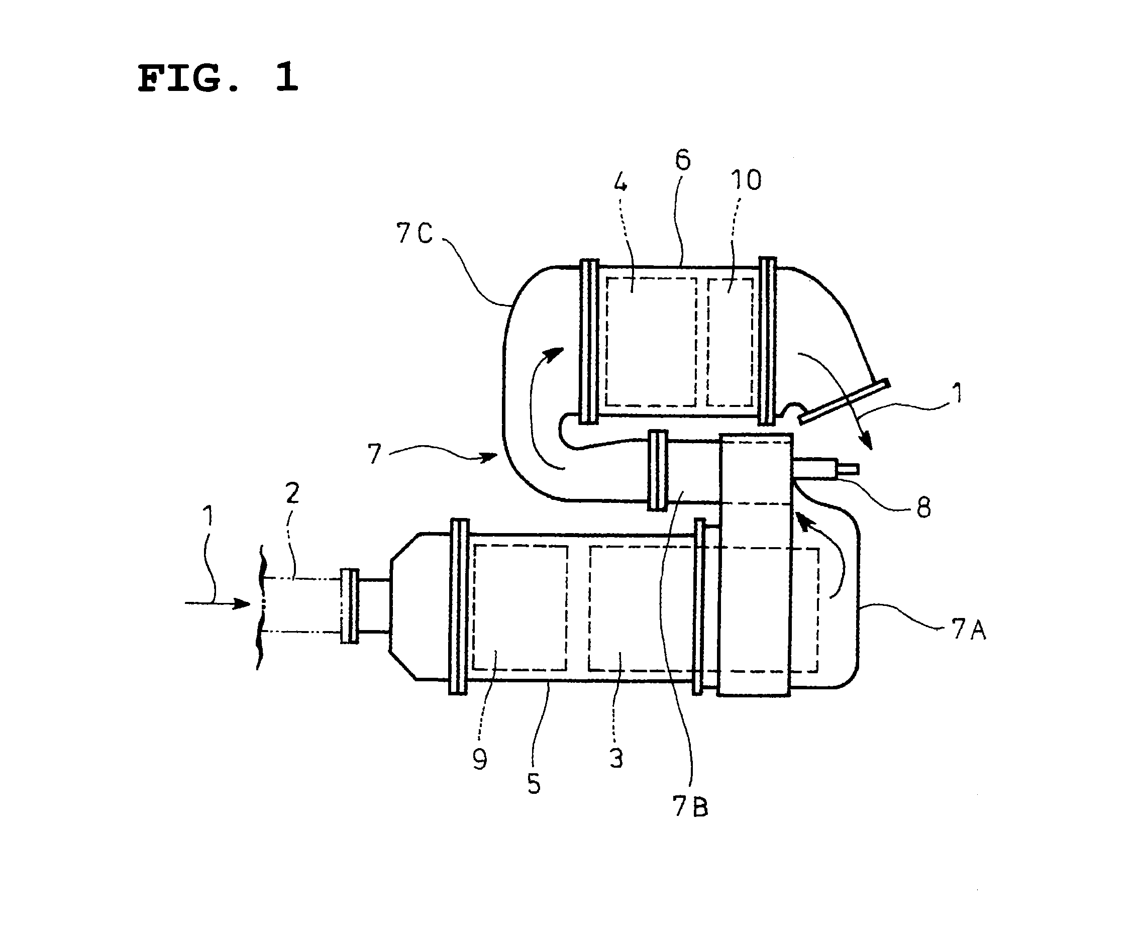
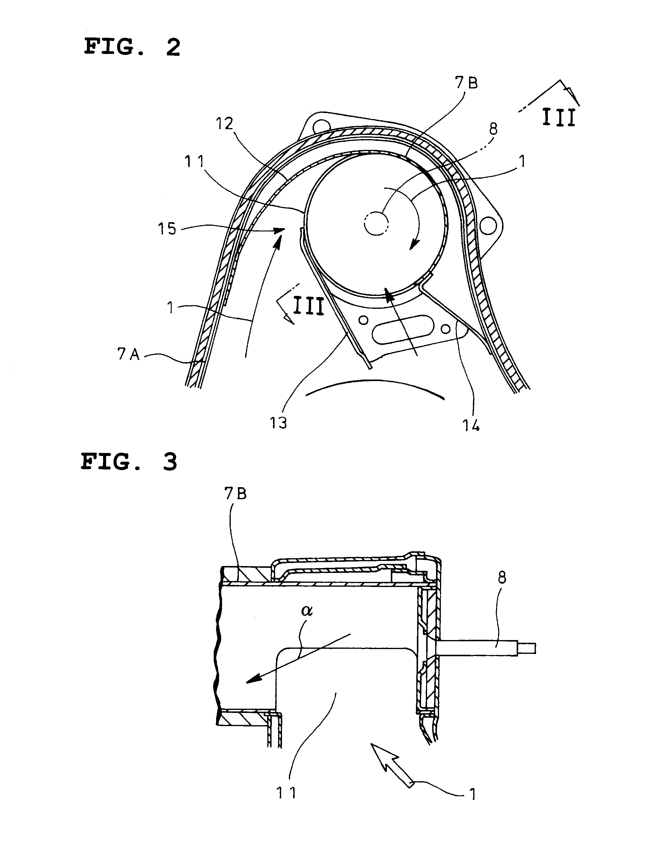
[0034]As shown in FIG. 4, the embodiment is characteristic in that opening sections 11 at an entry end of the mixing pipe 7B of the exhaust emission control device configured similarly to that illustrated in FIGS. 1-3 are formed along the swirling flow a of the exhaust gas 1 caused by the mixer structure 15 (see FIG. 2).

[0035]Specifically, unlike existing opening sections 11 each opened in a substantially simple rectangular shape as shown by a two-dot chain line in FIG. 4, one side 11a of the opening section 11 is formed along the swirling flow α, inclined at an angle X relative to a direction parallel to an axis of the mixing pipe 7B (O in FIGS. 4 and 5 represents the axis of the mixing pipe 7B) as shown by a solid line in FIG. 4.

[0036]Moreover, as shown in ...


PUM

PropertyMeasurementUnit
angleaaaaaaaaaa
distanceaaaaaaaaaa
sizeaaaaaaaaaa

Abstract

An exhaust emission control device comprises a selective reduction catalyst for reacting NOx in an exhaust gas with ammonia, means for adding a urea water into the exhaust gas upstream of the catalyst and a cylindrical mixing pipe as a connection between the adding means and the catalyst, an entry end of the mixing pipe being formed with circumferential opening sections and provided with guide fins for guiding the exhaust gas to the opening sections tangentially of the entry end to provide a mixer structure, the adding means being arranged centrally on the entry end of the mixing pipe and directed toward an exit end of the mixing pipe for addition of the urea water into a swirling flow of the exhaust gas caused by the mixer structure. The opening sections are formed along the swirling flow.

Description

TECHNICAL FIELD[0001]The present invention relates to an exhaust emission control device.BACKGROUND ART[0002]It has been recently considered to incorporate a particulate filter in an exhaust pipe for collection of particulates in an exhaust gas, a selective reduction catalyst capable of selectively reacting NO with ammonia even in the presence of oxygen being arranged downstream of the particulate filter, a urea water as a reducing agent being added between the selective reduction catalyst and the particulate filter, thereby achieving simultaneous reduction of the particulates and NOx.[0003]In such a case, the addition of the urea water to the selective reduction catalyst takes place between the particulate filter and the selective reduction catalyst; thus, in order to secure a sufficient reaction time for thermal decomposition of the added urea water into ammonia and carbon dioxide gas, it is necessary to lengthen a distance from an added position of the urea water to the selective...

Claims


Application Information

Patent Timeline
Patent Type & Authority Applications(United States)
IPC IPC(8): F01N3/20F01N3/28
CPCB01D53/9431F01N13/009B01D2251/2067F01N3/2066F01N3/28F01N13/02F01N13/141F01N2240/20F01N2490/00F01N2610/02F01N2610/1453Y02T10/24F01N3/2892F01N2470/00F01N13/0097B01D53/9477Y02T10/12
Inventor KOWADA, MINORU
Owner HINO MOTORS LTD
Why Eureka
Try Eureka