Heat dissipation device and manufacturing method thereof

a heat dissipation device and manufacturing method technology, applied in indirect heat exchangers, semiconductor/solid-state device details, lighting and heating apparatus, etc., can solve the problems of limiting the performance of the radiating fin, increasing the volume and weight of the heat dissipation device, and affecting the heat dissipation performance of the latest electronic components. , to achieve the effect of light weigh

Inactive Publication Date: 2012-10-11
ASIA VITAL COMPONENTS SHENZHEN CO LTD
View PDF20 Cites 4 Cited by
  • Summary
  • Abstract
  • Description
  • Claims
  • Application Information

AI Technical Summary

Benefits of technology

[0009]A primary object of the present invention is to provide a heat dissipation device and a manufacturing method thereof. The heat dissipation device has lighter weight.
[0010]A further object of the present invention is to provide the above heat dissipation device and manufacturing method thereof. The heat dissipation device has higher heat conduction efficiency and better heat dissipation performance.
[0011]To achieve the above and other objects, the heat dissipation device of the present invention includes a first chamber, a second chamber and multiple connection members. The first chamber defines therein a first cavity in which a working fluid is contained. The second chamber defines therein a second cavity. Each connection member has a first opening and a second opening at two ends. The first and second openings communicate with each other through a passageway. The first openings are connected with the first chamber. The second openings are connected with the second chamber. The first cavity of the first chamber communicates with the second cavity of the second chamber through the passageways. The working fluid in the first cavity is heated and evaporated into vapor. The vapor passes through the passageways into the second cavity. After reaching the second cavity, the vapor is condensed into liquid state. Then, the liquid goes back into the first cavity through the passageways to complete a working cycle and achieve heat dissipation effect. The heat dissipation device has much higher heat dissipation efficiency, smaller volume and lighter weight.

Problems solved by technology

To meet the requirements for high efficiency, integration and multifunctional application, it has become a great challenge how to satisfy the requirement for heat dissipation.
However, the convection thermal resistance still limits the performance of the radiating fins.
As a result, it is hard for the radiating fins to meet the heat dissipation requirement of the latest electronic components.
This leads to increase of volume and weight of the heat dissipation device.
Moreover, the evaporation and condensation of the heat conduction medium are both completed in the heat pipe 12 so that the heat dissipation efficiency of the heat dissipation device 10 is limited.
Therefore, the conventional heat dissipation device has the following shortcomings:1. The conventional heat dissipation device has large volume and heavy weight.2. The conventional heat dissipation device has limited heat conduction efficiency and poor heat dissipation performance.

Method used


Image

  • Heat dissipation device and manufacturing method thereof
  • Heat dissipation device and manufacturing method thereof
  • Heat dissipation device and manufacturing method thereof

Examples


Embodiment Construction

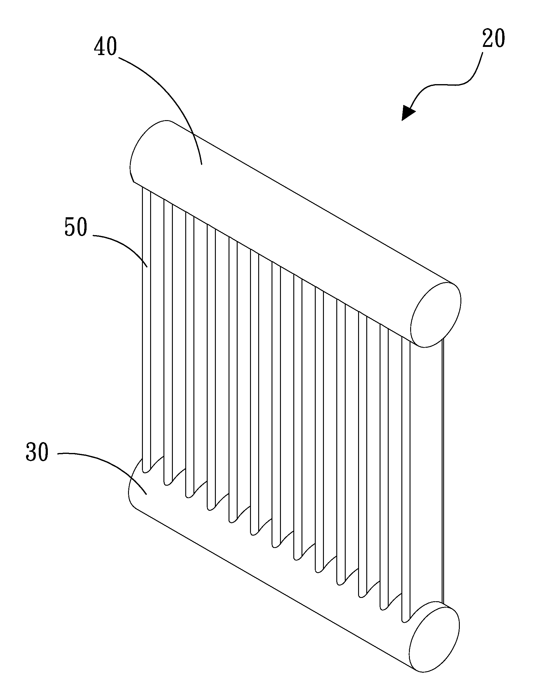
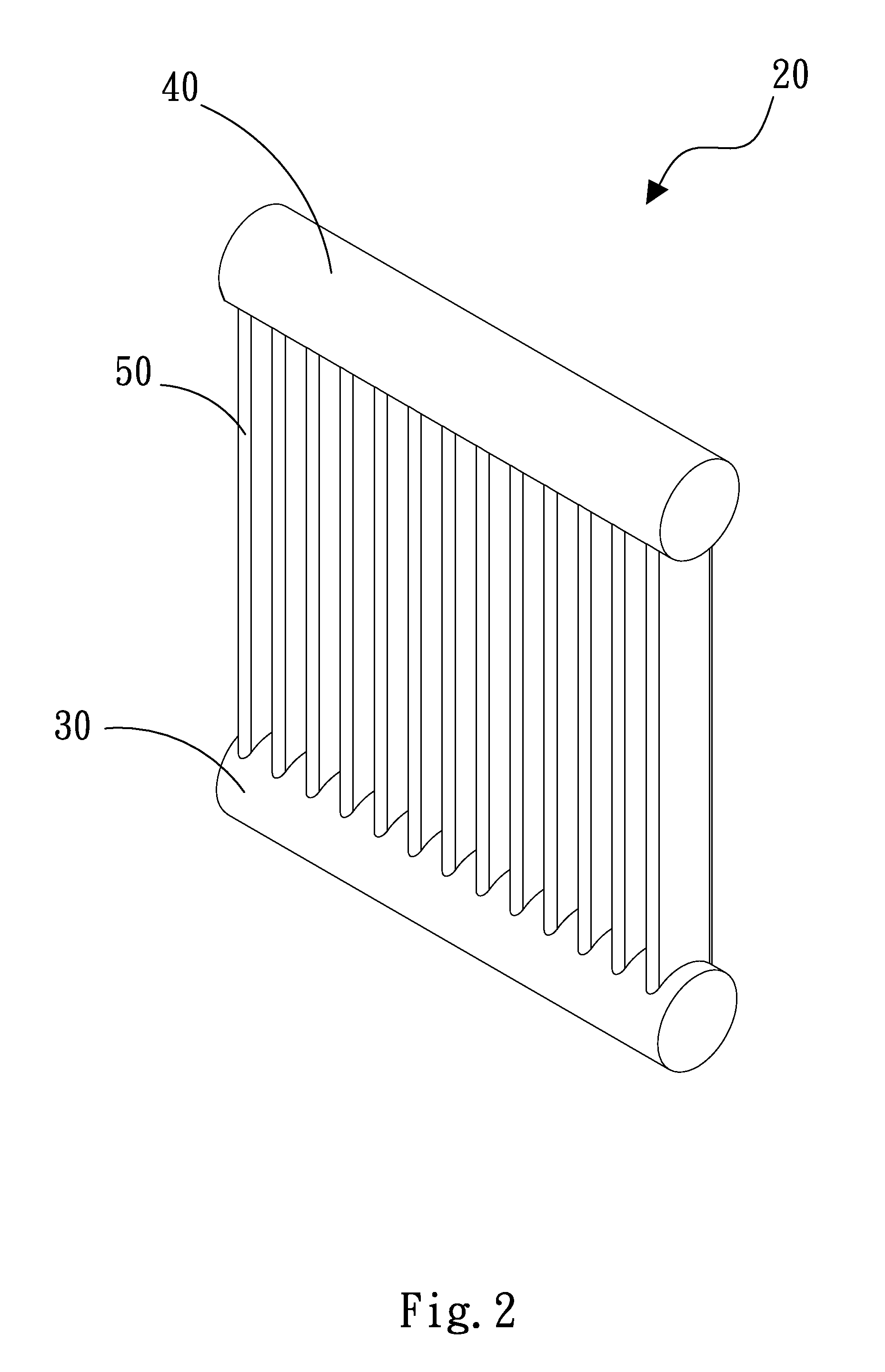
[0027]Please refer to FIGS. 2, 3 and 4. FIG. 2 is a perspective view of a first embodiment of the heat dissipation device of the present invention. FIG. 3 is a sectional view of the first embodiment of the heat dissipation device of the present invention. FIG. 4 is a sectional view according to FIG. 3, showing the operation of the heat dissipation device of the present invention. The heat dissipation device 20 of the present invention includes a first chamber 30, a second chamber 40 and multiple connection members 50.

[0028]The first chamber 30 defines therein a first cavity 31 in which a working fluid is contained. Each connection member 50 has a first opening 51 and a second opening 52 at two ends. The first and second openings 51, 52 communicate with each other through a passageway 53. The first openings 51 are connected with the first chamber 30. The first chamber 30 is formed with multiple first perforations 32 corresponding to the first openings 51 in position. The first openin...


PUM

PropertyMeasurementUnit
capillary structureaaaaaaaaaa
heat conduction efficiencyaaaaaaaaaa
heat dissipation performanceaaaaaaaaaa

Abstract

A heat dissipation device and a manufacturing method thereof. The heat dissipation device includes a first chamber defining a first cavity, a second chamber defining a second cavity, and multiple connection members each defining a passageway. First and second ends of the connection members are respectively connected with the first and second chambers in communication with the first and second cavities through the passageways. A working fluid is contained in the first cavity. When the working fluid is heated, the working fluid is evaporated into vapor. The vapor passes through the passageways into the second cavity. After reaching the second cavity, the vapor is condensed into liquid state. Then, the liquid goes back into the first cavity through the passageways to complete a working cycle and achieve heat dissipation effect.

Description

FIELD OF THE INVENTION[0001]The present invention relates to a heat dissipation device and a manufacturing method thereof. The heat dissipation device has higher heat conduction efficiency and better heat dissipation performance. Also, the weight of the heat dissipation device is lighter.BACKGROUND OF THE INVENTION[0002]Following the continuous advance of electronic industries, it has become a very important topic how to cool or remove heat of the heat sources. To meet the requirements for high efficiency, integration and multifunctional application, it has become a great challenge how to satisfy the requirement for heat dissipation. In modern electronic industries, the research for high-efficiency heat dissipation device has been more and more respected.[0003]Radiating fins are generally used to dissipate the heat generated by a heat generation component or system to the atmosphere. In condition of lower thermal resistance, the radiating fins have higher heat dissipation efficiency...

Claims


Application Information

Patent Timeline
Patent Type & Authority Applications(United States)
IPC IPC(8): F28F9/02B23P15/26
CPCB23P15/26F28D1/05366F28D15/0266F28D15/0283F28D15/04Y10T29/49389H01L23/427H01L2924/0002F28F1/126H01L2924/00
Inventor WU, WEN-YUANLU, CHIH-CHIEH
Owner ASIA VITAL COMPONENTS SHENZHEN CO LTD
Why Eureka
Try Eureka