Splitboard Bindings

a technology of splitboards and bindings, applied in the field of splitboard bindings, can solve the problems of increasing weight, instability, and decreasing the torsional stiffness (or spring constant) of the boot bindings, and the lack of prior art solutions is not surprising, so as to improve the splitboard ride, improve the performance of ski touring configuration, and facilitate the repositioning of the boots

Active Publication Date: 2012-10-11
SPARK R&D IP HLDG LLC
View PDF11 Cites 31 Cited by
  • Summary
  • Abstract
  • Description
  • Claims
  • Application Information

AI Technical Summary

Benefits of technology

[0026]Any solution to the problem must also allow the rider to easily reposition the boots when switching from snowboard riding to ski touring configuration, and the performance in ski touring configuration also must be improved.
[0027]The prior art adaptor mounting plate, which serves the function of adapting both snowboard-type soft-boot bindings and hard boot bindings to the snowboard mounting blocks and also to the ski touring mounting brackets of the prior art, can be advantageously eliminated. The adaptor mounting plate can be replaced with a box girder in which the top plate and “upper surface” of the box girder, on which the rider's boot is supported, and bottom plate with channel and inside flanges that grips the board, are joined by medial and lateral web spacer members having an aspect ratio different or modified from the aspect ratios of the top and bottom plate members. The aspect ratio of the web spacers may be varied from heel to toe, so that the box girder is shaped, proportioned and contoured to better support and secure the rider's boot. Stiffer torsional spring constants are obtained with the wider boot bindings of this construction, and interestingly, because of the integrated design, the overall height of the raised platform nonetheless places the rider in a position that is lower than possible with the devices of the prior art. While not being bound by theory, these teachings are a new solution to the problem of boot binding structural mechanics, and are shown here to have unexpected advantages that improve the splitboard ride.
[0028]The modified box girder serves dual functions in securing the boot on top and gripping the board with its lower aspect, while remaining itself structurally rigid. By limiting play and compliance between the girder and the board surface, the overall spring constant becomes relatively constant over the required flexural range, and approximates the spring constant of the boot itself, as modified by reinforcing structures such as boot pocket, upper side rails, heel cup, and highback, all of which increase stiffness adjustably.
[0029]By eliminating the adaptor mounting plate, and subsuming its functions as part of an integral boot binding lower, multiple improvements in form and function are achieved. Unneeded weight is eliminated. Reduction in heel height relative to the board surface results in a lower center of gravity on the board, for better balance and control. Recognizing the inherent plasticity of the mounting blocks, clearance spaces between the bottom surface of the box girder and the upper face of the board are reduced or eliminated, dramatically firming the spring constant for the bindings. Removal of the narrow adaptor mounting plate also increases the firmness of the foot and ankle contact with the board surface, and eliminates the looseness, flex, or “play” between the multiple mechanical components of the prior art that dampen the board's responsiveness to the rider's movements. This has proved an elegant solution to what was an unrecognized problem.
[0030]Happily, free heel ski performance is also improved. For one, by replacing the pivot pin used with the prior art adaptor mounting plate with a longer pivot pin mounted through the thick webs or spacers of the structural girder at the toe of the integral boot binding lower, wear on the parts is dramatically reduced. In the embodiment of Example 1, the pivot pin is lubricated and reinforced by ultrahigh molecular weight polyethylene (UHMWPE) used as a spacer material in the toe of the integral boot binding lower. This eliminates oval mounting-hole deformation characteristic of prior art pivot pin mounting cradles. Again, broader and more firm toe contact with the board is obtained, improving performance in free heel skiing. Snow, which invariably can pack up under the boots and mounting blocks during skiing and snowboarding, is vented out under the heel, easing the switch from ski touring to snowboard riding configuration, and vice versa.
[0031]The use of variform box girder construction, where the web aspect ratio is varied independently of the aspect ratios of the top and bottom plate members of the girder, permits shaping, proportioning and contouring the top surface of the binding to the sole of the rider's boot, while preserving the fixed dimensions of the channel and inside flanges of the bottom plate. As demonstrated here, control of the board is improved by eliminating cumulative elastic and inelastic deformation that is readily observable in boot bindings of the prior art (see Examples 2 and 4). The binding is configured so that bottom medial and lateral flanges touch down on the board face during maneuvers. Comparative field studies performed with embodiments of this invention show that torsional stiffness is increased to a efficacious level, resulting in improved control and comfort for the splitboard rider.

Problems solved by technology

This approach is problematic, adding weight, instability, and decreasing the torsional stiffness (or spring constant) of the boot bindings.
The lack of a prior art solution is not surprising because the problem has not previously been recognized in these terms.

Method used


Image

  • Splitboard Bindings
  • Splitboard Bindings
  • Splitboard Bindings

Examples


example 1

[0200]A Drake F-60 snowboard binding with integral heel cup and highback was modified in a shop by removing the upper binding baseplate (32) and 4-hole disk and substituting in their place a sheet of 2.5 mm aluminum with side rails folded up to form a shallow channel for the boot.

[0201]A three dimensional CAD design was sent to a local sheetmetal house that used a CNC (computer numerically controlled) laser cutter to cut the outline and holes for the aluminum parts necessary for the bindings. Sheetmetal press brakes were then used to bend the channels of the bindings. Similarly, a CNC milling machine cut out the UHMW polyethylene spacers from a sheet of 16 mm thick plastic. This machine provided all holes, the outline, and contoured surfaces.

[0202]Using mounting bolts, the heel and toe straps and highback were secured in place. A total of 10 screws, countersunk, were placed at the circumference of the base along each side of the sandwich to secure the plastic spacer materials (webs)...

example 2

[0205]Mechanical comparisons were made using a splitboard and boot binding assembly of the prior art versus that of Example 1. A Voile “Splitdecision 166” splitboard was used for the comparisons, and for the prior art testing, Drake F-60 snowboard bindings were mounted as recommended by the manufacturer on the Voile mounting hardware. The boot bindings were assembled in snowboard riding configuration for these comparisons.

[0206]Physical measurements of the two boot bindings were also made and are recorded in Table I.

TABLE IPrior ArtExample 1Distance from plane of board to bottom of boot 26 mm 14 mmWidth in contact with board under lateral load 80 mm 120 mmWeight per boot binding1182 g1015 g

[0207]To measure deformation under lateral strain, which is related to spring constant K of the boot bindings, the snowboard was clamped to a vertical surface so that the highback of the boot bindings were mounted parallel to the floor. An 11.3 kg weight was then clipped onto the top of the highba...

example 3

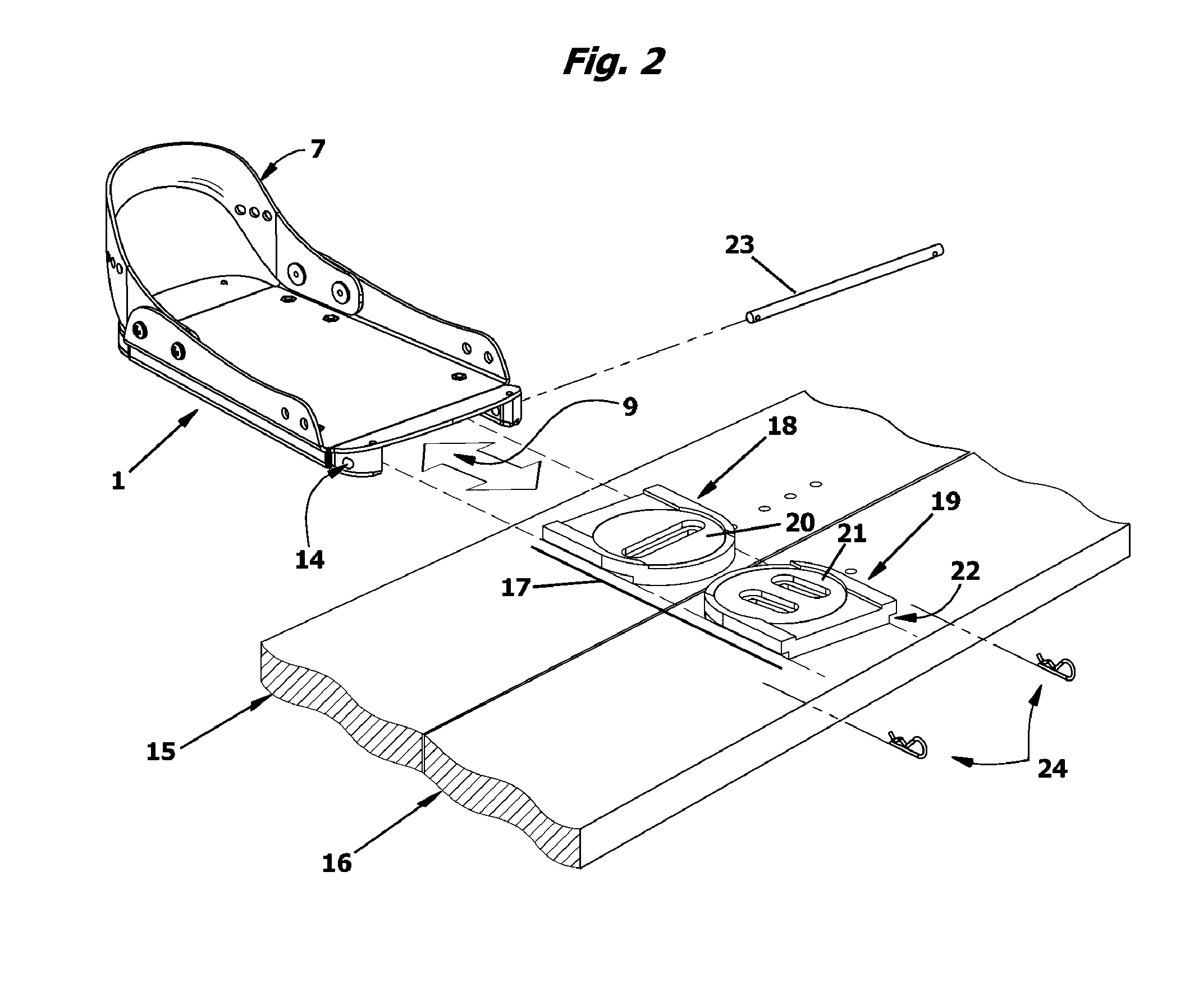
[0211]A torsional stiffness coefficient was measured for the boot binding of FIG. 33 and compared to an equivalent measurement for a binding of the prior art (FIG. 4B). However, in order to eliminate the contribution of the upper baseplate 32, four hole disk 31 and gasket 39, these were eliminated from the test setup. To make the measurement, a lever arm consisting of a block of aluminum 7.7 inches long by 2.5 inches by 2.5 inches wide was bolted to the slider track 40 of the prior art setup or to the top plate member 3 of the inventive article of FIG. 33. A block and tackle was used to apply a force on the lever arm, which generated a torque on the binding. An angle gauge was mounted on the aluminum block to measure theta. Both boot bindings were mounted on identical mounting blocks (17—FIG. 2) which had been affixed to a splitboard for the test. The splitboard was clamped to a solid support. Deformation (as torsional rotation) versus torque was then measured. The data is plotted i...


PUM

PropertyMeasurementUnit
weightaaaaaaaaaa
weightaaaaaaaaaa
weightaaaaaaaaaa

Abstract

Splitboard boot bindings for backcountry splitboarding. Each of a pair of soft-boot bindings is provided with an integral boot binding lower that conjoins the two halves of a splitboard without the additional weight or height of an adaptor mounting plate, upper binding baseplate or “tray”, and extra fasteners of the prior art. The boot binding lower is formed as a box girder and provides improved torsional stiffness for splitboard riding. When subjected to a torque applied by the rider, the bottom mediolateral edges of the box girders are configured to contactingly engage the top face of the splitboard, thereby dynamically coupling the rider's boot sole and the board via a single rigid structure. In a preferred embodiment, the web or “spacer” members of the box girder are characterized by an aspect ratio or contour height that is varied from heel to toe.

Description

RELATED APPLICATIONS[0001]This application is a Continuation-in-Part and claims the benefit under 35 U.S.C. §120 of U.S. patent application Ser. No. 12 / 483,152 filed on Jun. 11, 2009, now U.S. Pat. No. ______, which is a Continuation-in-Part and claims the benefit under 35 U.S.C. §120 of U.S. patent application Ser. No. 11 / 409,860 filed on Apr. 24, 2006, now U.S. Pat. No. 7,823,905, which claims priority under 35 U.S.C. §119(e) from U.S. Provisional Patent Application No. 60 / 792,231 filed Apr. 14, 2006 and U.S. Provisional Patent Application No. 60 / 783,327 filed Mar. 17, 2006; all said priority documents are incorporated herein in entirety by reference.BACKGROUND OF THE INVENTION[0002]Backcountry snowboarding appeals to riders who wish to ride untracked snow, avoid the crowds of commercial resorts, and spurn limitations on what and where they can ride. There are no ski-lifts in the backcountry, so the snowboarder must climb the slopes by physical effort. Some snowboarders simply car...

Claims


Application Information

Patent Timeline
Patent Type & Authority Applications(United States)
IPC IPC(8): A63C9/18
CPCA63C5/02A63C5/03A63C9/006A63C10/28A63C2203/06A63C9/02Y10T29/49716A63C5/033A63C9/20A63C10/20
Inventor RITTER, WILLIAM J.
Owner SPARK R&D IP HLDG LLC
Why Eureka
Try Eureka