
Electric vehicle charge control system

a technology for electric vehicles and control systems, applied in charging stations, electric devices, transportation and packaging, etc., can solve the problems of undesirable battery full charge, short distance that can be traveled by electric vehicles per battery charge, and insufficient storage level of present batteries, so as to prevent the depletion of batteries and prolong the life of batteries

Active Publication Date: 2012-10-11
HONDA MOTOR CO LTD
View PDF4 Cites 94 Cited by
  • Summary
  • Abstract
  • Description
  • Claims
  • Application Information

AI Technical Summary

Benefits of technology

[0007]It is desirable to provide an electric vehicle charge control system capable of preventing the depletion of a battery and extending the life of the battery.
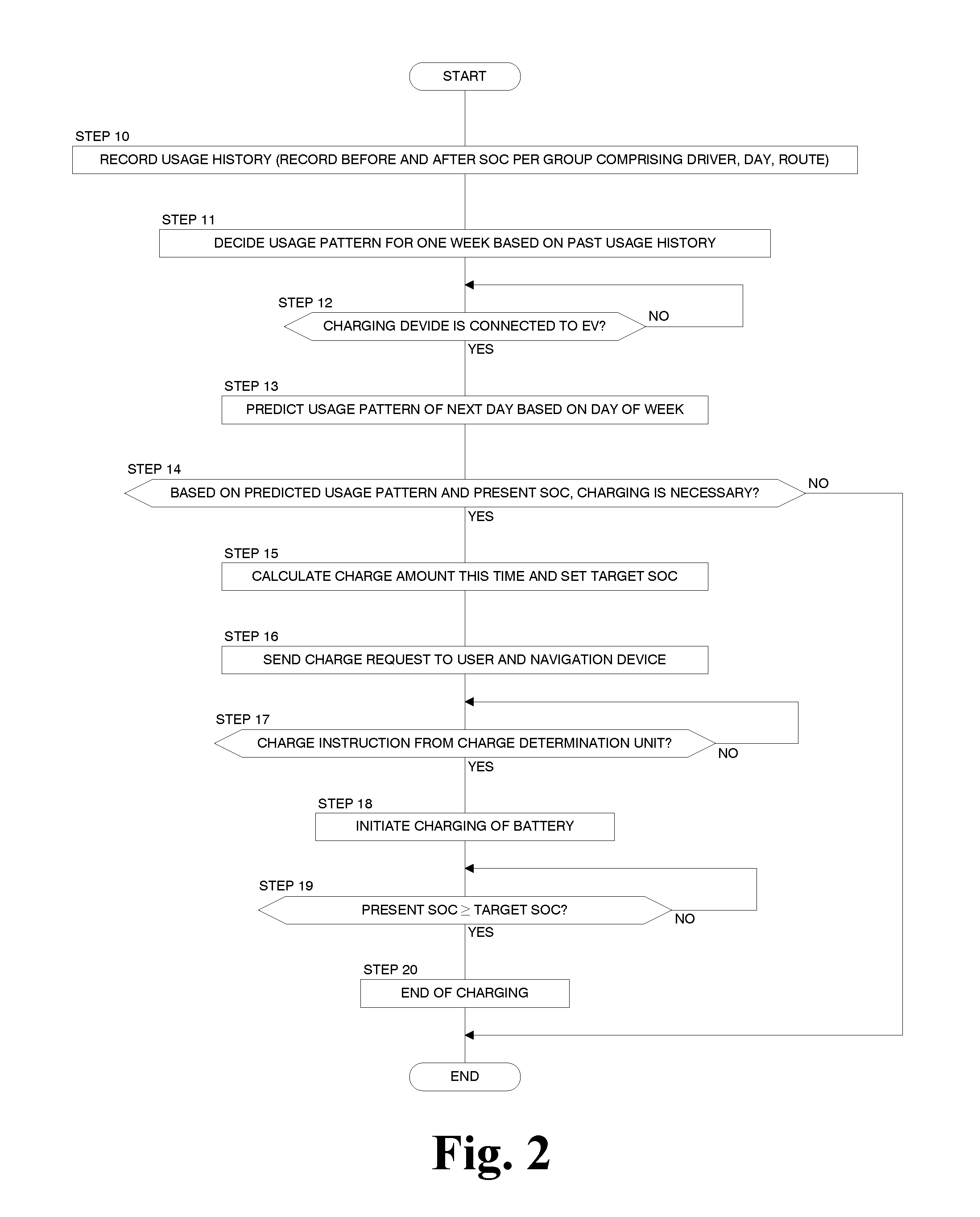
[0009]According to an embodiment of the present disclosure, the future amount of power consumption of the electric vehicle is predicted from the period-by-period usage history. On the basis of the predicted future amount of power consumption and the remaining amount or power of the battery, the determination of whether charging of the battery is necessary and the calculation of the target remaining amount of power are performed. On the basis of results of the determination and the calculation, the battery is charged. Accordingly, the number of charges of the battery can be reduced, and the remaining amount of power after charging can be reduced from the largest remaining amount of power at the time of full charge of the battery. It is therefore possible to extend the life of the battery while preventing battery depletion during the travel of the electric vehicle.
[0011]There is commonality among the electric vehicle usage patterns of general users on each day of the week, holidays, or weekdays. Accordingly, the history recording unit records the daily usage history as the period-by-period usage history. The charge determination unit determines the daily pattern of the electric vehicle including the amount of power consumption on the basis of the daily usage histories, predicts the future amount of power consumption on a future day from the daily pattern, and performs the determination of whether charging of the battery is necessary and the calculation of the target remaining amount of power on the basis of the predicted future amount of power consumption and the current remaining amount of power of the battery. As a result, it is possible to increase the accuracy of determining whether the charging of the battery is necessary and the accuracy of calculating the target remaining amount of power.
[0013]According to an embodiment of the present disclosure, a driver on the next day is predicted, the target remaining amount of power is calculated on the basis of the predicted driver, and the battery is charged on the basis of the target remaining amount of power. Accordingly, even in a case where the amount of power consumption of the electric vehicle varies from driver to driver, the remaining amount of power after the operation of the electric vehicle on the next day can be balanced. It is therefore possible to prevent the next battery charging time from being brought forward and prevent the battery from being unnecessarily charged to the level of a full charge.
[0015]According to an embodiment of the present disclosure, in a case where the predicted next charging day is postponed for one or more days by setting the larger target remaining amount of power that is larger than the standard target remaining amount of power, the target remaining amount of power is changed from the standard target remaining amount of power to the larger target remaining amount of power. As a result, it is possible to reduce the number of charges of the battery and extend the life of the battery.
[0016]Furthermore, according to an embodiment of the present disclosure, in a case where the next charging day predicted when the standard target remaining amount of power is set as the target remaining amount of power and the next charging day predicted when the smaller target remaining amount of power that is smaller than the standard target remaining amount of power is set as the target remaining amount of power are the same, the target remaining amount of power is changed from the standard target remaining amount of power to the smaller target remaining amount of power. As a result, it is possible to sufficiently reduce the target remaining amount of power from the level of a full charge without increasing the number of charges. This leads to the increase in the life of the battery.

Problems solved by technology

The storage level of present batteries is not sufficiently high, and a distance that can be traveled by an electric vehicle per battery charge is short.
On the other hand, from the viewpoint of extending the life of a battery, the full charge of the battery is undesirable.

Method used


Image

  • Electric vehicle charge control system
  • Electric vehicle charge control system
  • Electric vehicle charge control system

Examples


Embodiment Construction

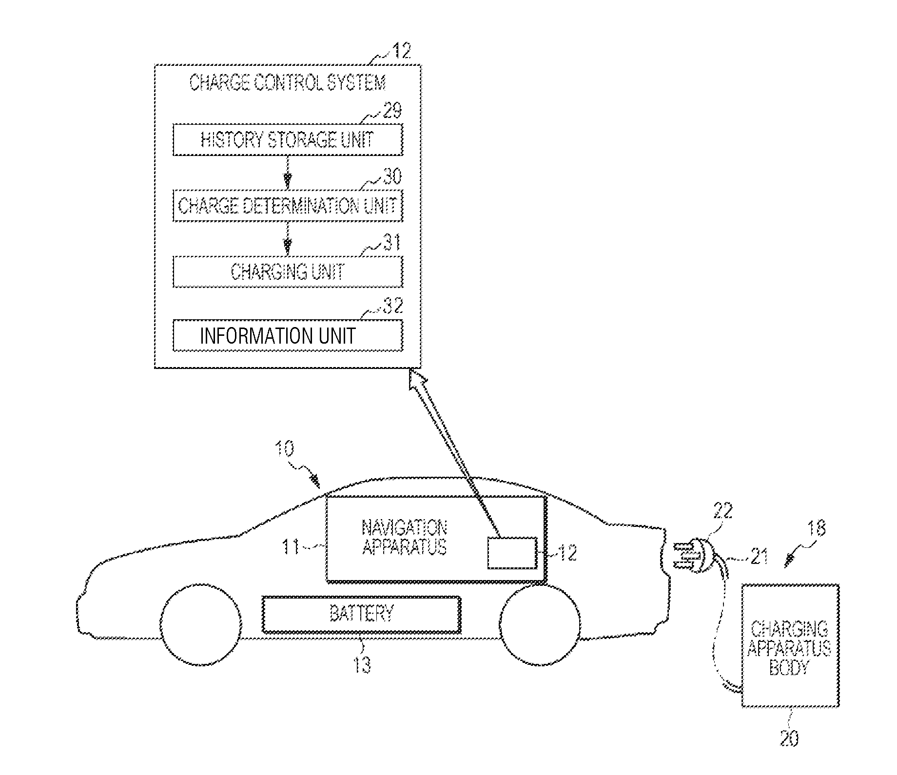
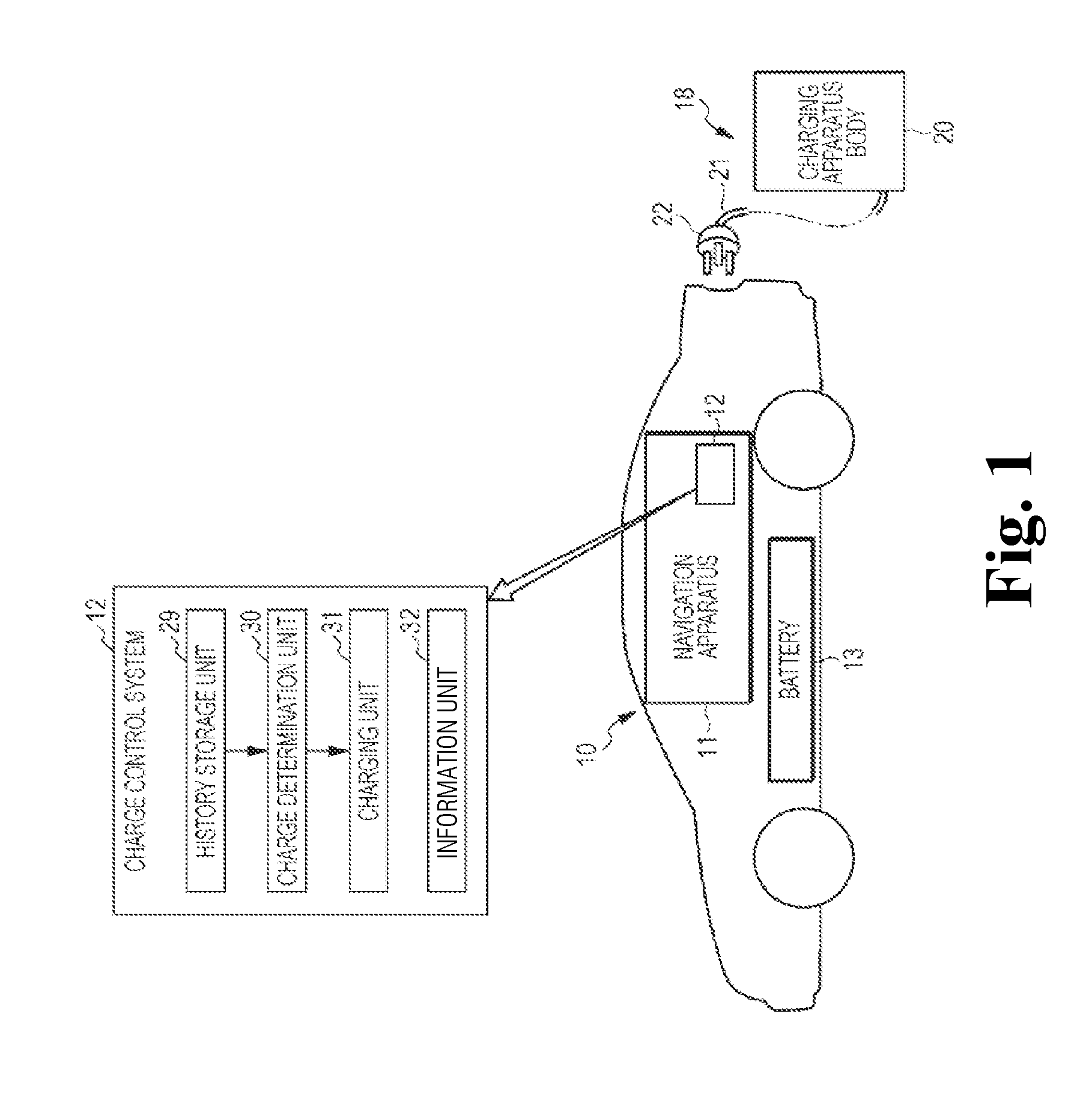
[0027]Referring to FIG. 1, an electric vehicle 10 includes a battery 13 for supplying electric power to an electric motor (not illustrated) for driving tires of the electric vehicle 10 and a navigation apparatus 11 including a charge control system 12. In the electric vehicle 10, the charge control system 12, which is included in the navigation apparatus 11, may be separated from the navigation apparatus 11. The configuration of the navigation apparatus 11 will be described in detail later with reference to FIG. 7 along with the description of the relation of connection between the navigation apparatus 11 and a communication control unit 35.

[0028]A charging apparatus 18 is disposed at the house and office of an owner of the electric vehicle 10, and will be disposed at a charging stand along a public road in the future. The charging apparatus 18 includes a charging apparatus body 20 and a plug 22 attached to the leading end of a cord 21 extending from the charging apparatus body 20. ...


PUM


Abstract

The usage pattern of an electric vehicle including the amount of power consumption of a battery on each day of the week is extracted from usage histories of the vehicle in a predetermined period. When the vehicle goes home after one day's operation and is connected to a charging apparatus, a charge determination unit predicts a usage pattern of the vehicle on the next day and determines whether the vehicle can operate on the next day with the remaining amount of power of a battery in the vehicle. When it is determined that the charging of the battery is necessary, the battery is charged until it reaches the target remaining amount of power. The target remaining amount of power is determined on the basis of the amount of power consumption in the predicted usage pattern so that the full charge is prevented and the number of charges is reduced.

Description

CROSS REFERENCES TO RELATED APPLICATIONS[0001]The present application claims priority under 35 U.S.C. §119 to Japanese Patent Application No. 2011-085801, filed Apr. 7, 2011, entitled “Electric Vehicle Charge Control System.” The contents of this application are incorporated herein by reference in their entirety.TECHNICAL FIELD[0002]The present disclosure relates to an electric vehicle charge control system for controlling charging of a battery included in an electric vehicle.BACKGROUND OF THE INVENTIONDescription of the Related Art[0003]Electric vehicles include batteries for supplying electric power to an electric motor. The storage level of present batteries is not sufficiently high, and a distance that can be traveled by an electric vehicle per battery charge is short. Accordingly, the general users of electric vehicles tend to relatively frequently charge batteries in the electric vehicles at home or a charging stand, and tend to fully charge the batteries at the time of each c...

Claims


Application Information

Patent Timeline
IPC IPC(8): H02J7/00B60L3/00H02J7/02H02J13/00
CPCB60L3/12B60L11/1816H02J7/0004Y02T90/121Y02T10/7005Y02T90/14Y02T10/7088H02J7/0073Y02T10/7072B60L53/14H02J7/0071H02J7/00036H02J7/00047Y02T10/70Y02T90/12
Inventor HAYASHI, MASANORITAKEMASA, KOICHIROTSURUTANI, TAISUKE
Owner HONDA MOTOR CO LTD
Learn More