Liquid crystal display device

a display device and liquid crystal technology, applied in non-linear optics, instruments, optics, etc., can solve the problems of non-uniform electric field intensity and reduced display mode efficiency, and achieve the effect of improving display mode efficiency

Active Publication Date: 2012-10-11
JAPAN DISPLAY INC
View PDF8 Cites 30 Cited by
  • Summary
  • Abstract
  • Description
  • Claims
  • Application Information

AI Technical Summary

Benefits of technology

[0010]The present invention has been made in consideration of these problems, and an object of the present invention is to provide a l

Problems solved by technology

That is to say, there is concern that the electric field intensity is non-u

Method used


Image

  • Liquid crystal display device
  • Liquid crystal display device
  • Liquid crystal display device

Examples


first embodiment

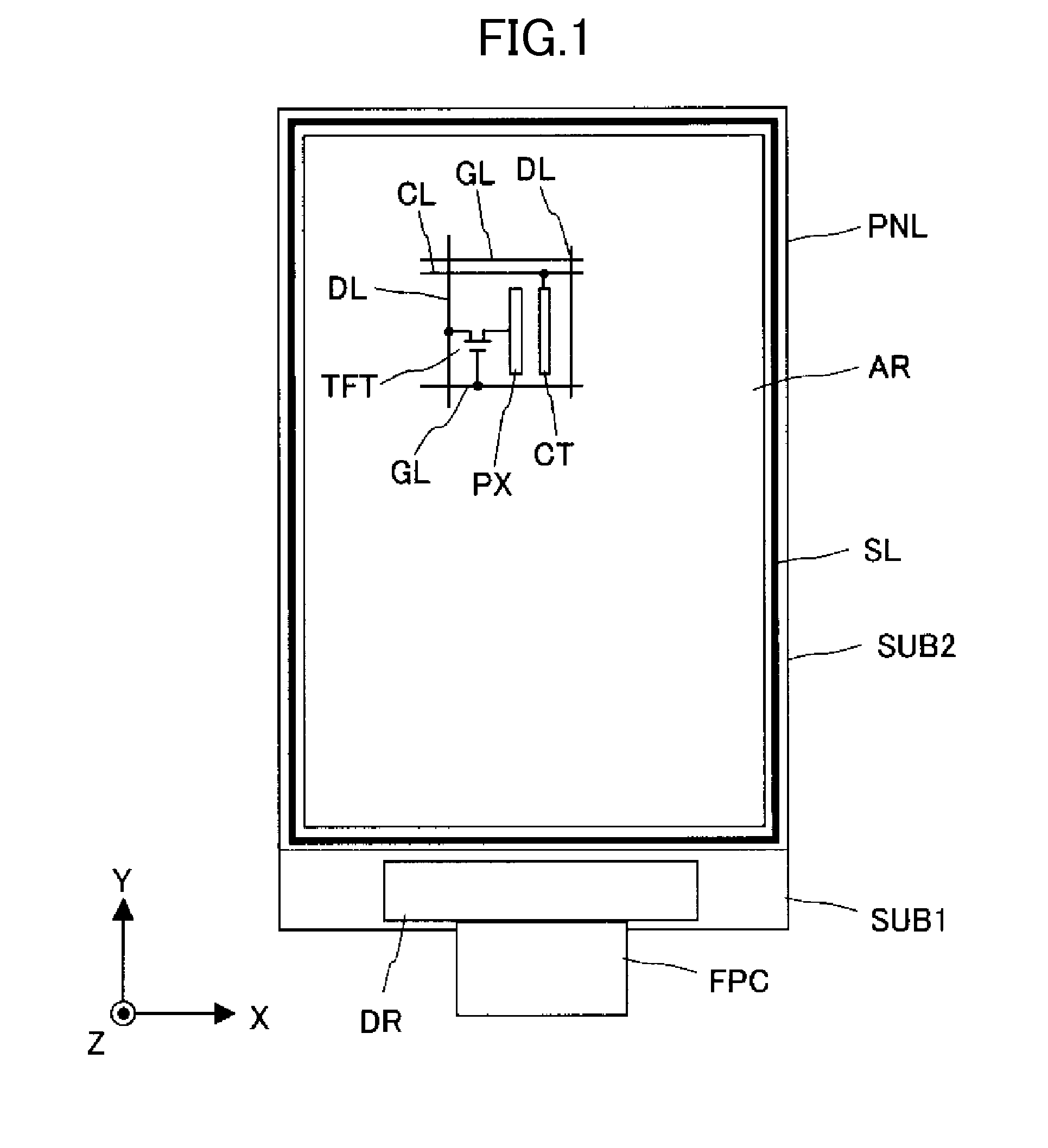
[0042]Overall Configuration

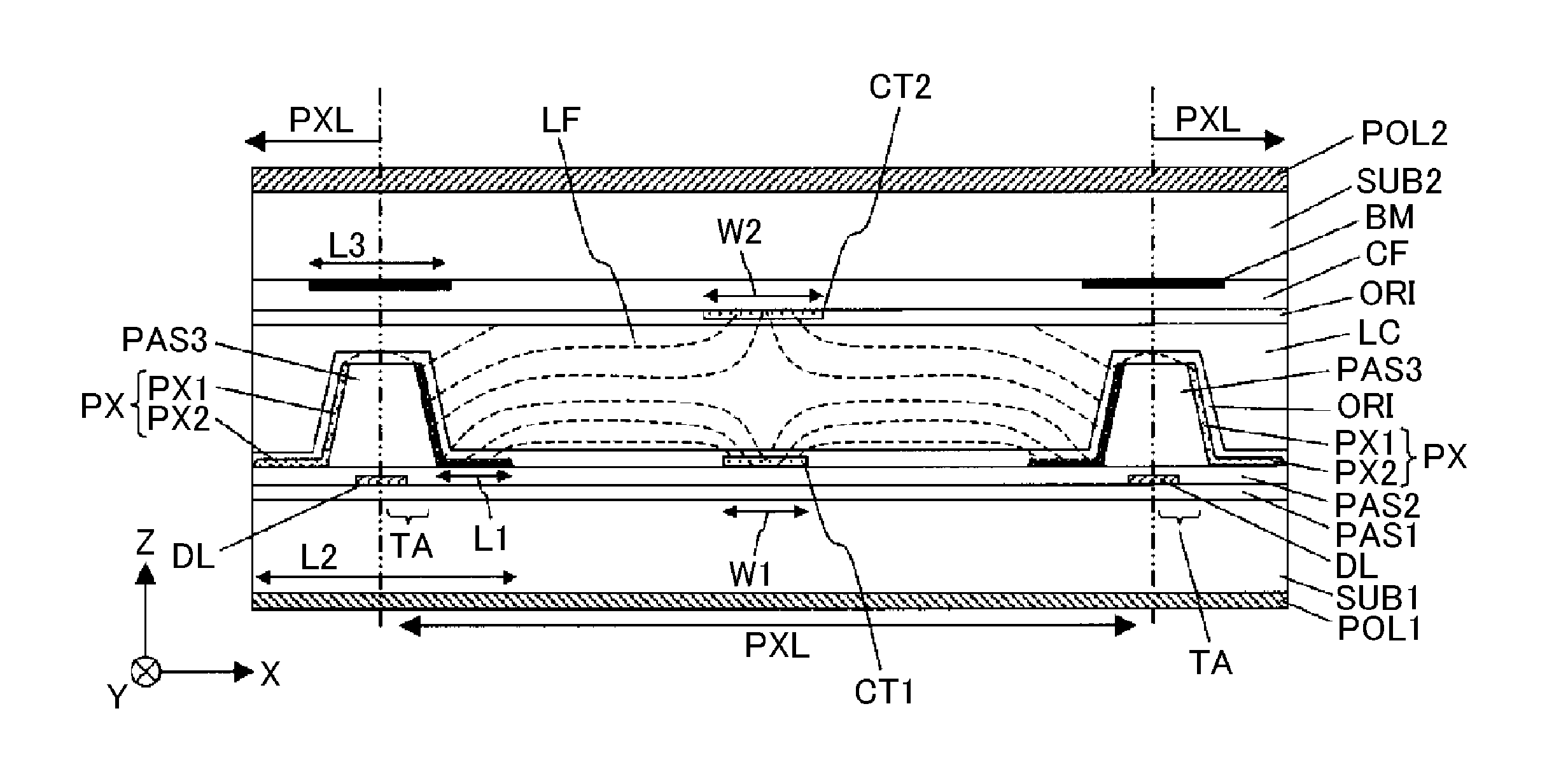
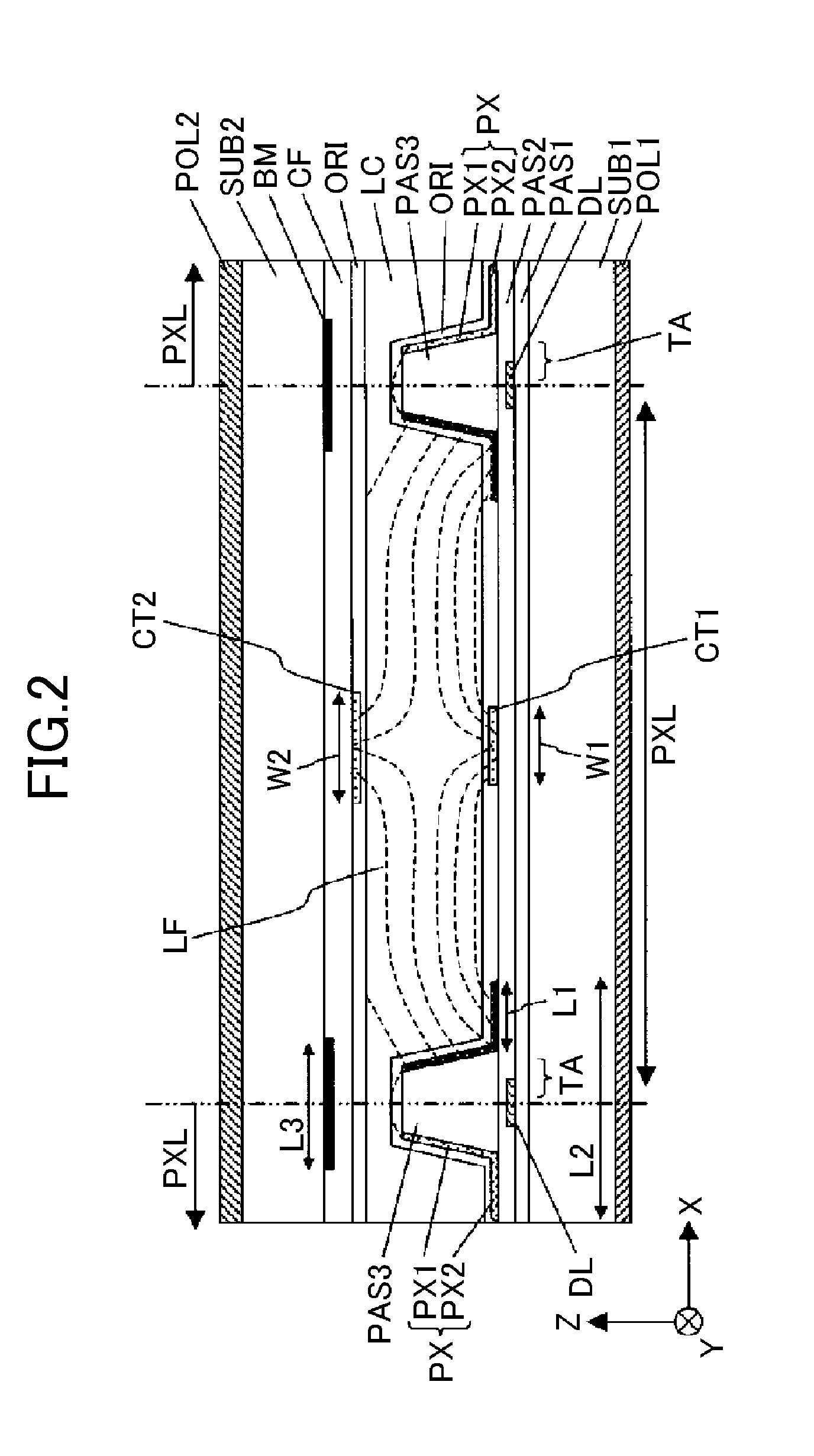
[0043]FIG. 1 is a diagram illustrating a pixel configuration of the liquid crystal display device according to a first embodiment of the present invention, and an overall configuration of the liquid crystal display device according to the first embodiment will be described with reference to FIG. 1. In addition, in the present specification, transmittance excluding influence of absorption by a color filter CF or polarizers POL1 and POL2 or influence of an aperture ratio is assumed as display mode efficiency. Therefore, when an oscillation direction of linearly polarized light emitted from the polarizer POL1 on the backlight unit side is incident to the polarizer POL2 on the display surface side, display mode efficiency in a case of being rotated by 90 degrees is assumed as 100%.

[0044]As shown in FIG. 1, the liquid crystal display device according to the first embodiment has a liquid crystal display panel PNL which includes a first substrate SUB1 provided wi...

second embodiment

[0089]FIG. 8 is a cross-sectional view illustrating a pixel configuration in a liquid crystal display device according to the second embodiment of the present invention, and the liquid crystal display device according to the second embodiment will be described with reference to FIG. 8. Here, the liquid crystal display device according to the second embodiment is different from the liquid crystal display device according to the first embodiment only in that cover electrodes CE are formed at the lower layer of the drain lines DL which are wires, that is, on the first substrate SUB1 side, and other configurations are the same. Therefore, in the following description, the cover electrodes CE will be described in detail. In addition, in the following description, a case where the cover electrodes CE are formed at the lower layer of the drain lines DL which are wires will be described; however, the cover electrodes CE may be formed at the lower layer of the gate lines. In addition, the co...

third embodiment

[0114]FIG. 14 is a cross-sectional view illustrating a pixel configuration in a liquid crystal display device according to a third embodiment of the present invention, and FIG. 15 is a cross-sectional view illustrating a detailed configuration of the wall electrode according to the third embodiment of the present invention. Here, the liquid crystal display device according to the third embodiment is different from the liquid crystal display device according to the first embodiment only in the configuration of the wall electrode PX formed on the first substrate SUB1 side, and other configurations are the same. Hereinafter, in the following description, a configuration of the wall electrode PX will be described in detail. In addition, in the liquid crystal display device according to the third embodiment as well, although a case will be described in which the wall electrodes PX at both ends of the pixel PXL are pixel electrodes and the pseudo-wall electrode CT is a common electrode, t...


PUM


Abstract

A liquid crystal display device includes a first substrate provided with first and second electrodes, and a second substrate disposed to be opposite to the first substrate via a liquid crystal layer. Regions of pixels each having the first and second electrodes are arranged in a matrix, and the liquid crystal layer is driven by an electric field in an in-plane direction of the first substrate, applied between the first and second electrodes. A step difference is formed at an opposite side of the first substrate for each of the pixel regions. The first or second electrode includes a wall-shaped electrode formed at a side wall surface of the step difference and a planar electrode formed from an edge of the wall-shaped electrode along the main surface of the first substrate. The wall-shaped electrode and the planar electrode are electrically connected to each other.

Description

CROSS-REFERENCE TO RELATED APPLICATION[0001]The present application claims priority from Japanese application JP 2011-083815 filed on Apr. 5, 2011, the contents of which are hereby incorporated by reference into this application.BACKGROUND OF THE INVENTION[0002]1. Field of the Invention[0003]The present invention relates to a liquid crystal display device, and more particularly to an active matrix type liquid crystal display device.[0004]2. Description of the Related Art[0005]In recent years, performance of the liquid crystal display device has been increasingly improved, and thus there is a demand for products capable of performing WVGA display of 800×480 pixels even in small and medium-size liquid crystal display devices of 3 to 4 inches. However, in small and medium-size liquid crystal panels capable of performing the WVGA display, since plural display pixels (hereinafter, simply referred to as pixels) are required to be formed in a limited display region, the width of a single p...

Claims


Application Information

Patent Timeline
IPC IPC(8): G02F1/1343
CPCG02F2201/122G02F1/134363G02F1/1343
Inventor HIRATSUKA, TAKATOITOU, OSAMUOKA, SHINICHIROKOMURA, SHINICHI
Owner JAPAN DISPLAY INC
Why Eureka
Try Eureka