
Method and Apparatus for Multi-Radio Coexistence on Adjacent Frequency Bands

a technology of adjacent frequency bands and radios, applied in the field of improving the coexistence of radios operating in adjacent frequency spectrum or bands, can solve the problems of reducing data throughput or service quality, interference may occur at a reception radio frequency, and loss of connectivity

Active Publication Date: 2012-10-11
GOOGLE TECH HLDG LLC
View PDF5 Cites 197 Cited by
  • Summary
  • Abstract
  • Description
  • Claims
  • Application Information

AI Technical Summary

Problems solved by technology

Note that interference may occur at a reception radio frequency or at any intermediate frequency used within a receiving device for the purpose of demodulation.
Without coexistence mechanisms, radio frequency interference can cause, amongst other degradations, loss of connectivity, decreased data throughput or reduction in quality of service, or increased current drain.
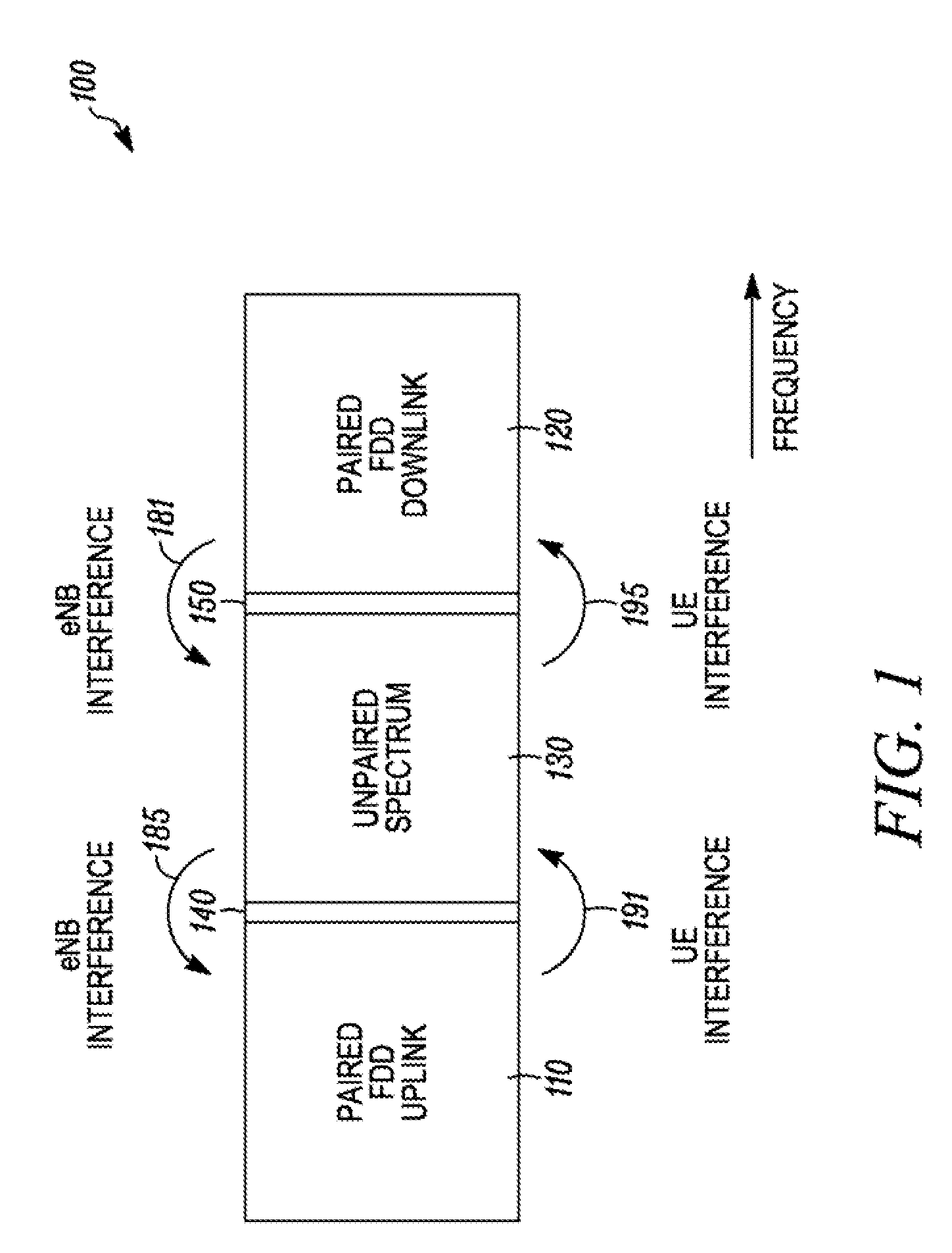
When adjacent radio frequency bands are allocated to different uses, wireless interference can result.
In general, there is an elevated risk of wireless interference when a frequency band used for uplink transmissions is adjacent to a frequency band used for downlink transmissions; the wireless transmissions in one band can create interference for wireless receivers operating in the adjacent band.
Although this is feasible at base stations, improved filtering and antenna separation may be difficult or prohibitively expensive to implement in user equipment where physical constraints (such as small dimensions which result in low coupling losses between transmitting and receiving antennas) and low cost targets apply.
Because multiple radios can wirelessly interfere with each other in various ways, and effective filtering may not be available at a reasonable cost, coexistence mechanisms should be developed for a variety of collocated and non-collocated scenarios.

Method used


Image

  • Method and Apparatus for Multi-Radio Coexistence on Adjacent Frequency Bands
  • Method and Apparatus for Multi-Radio Coexistence on Adjacent Frequency Bands
  • Method and Apparatus for Multi-Radio Coexistence on Adjacent Frequency Bands

Examples


Embodiment Construction

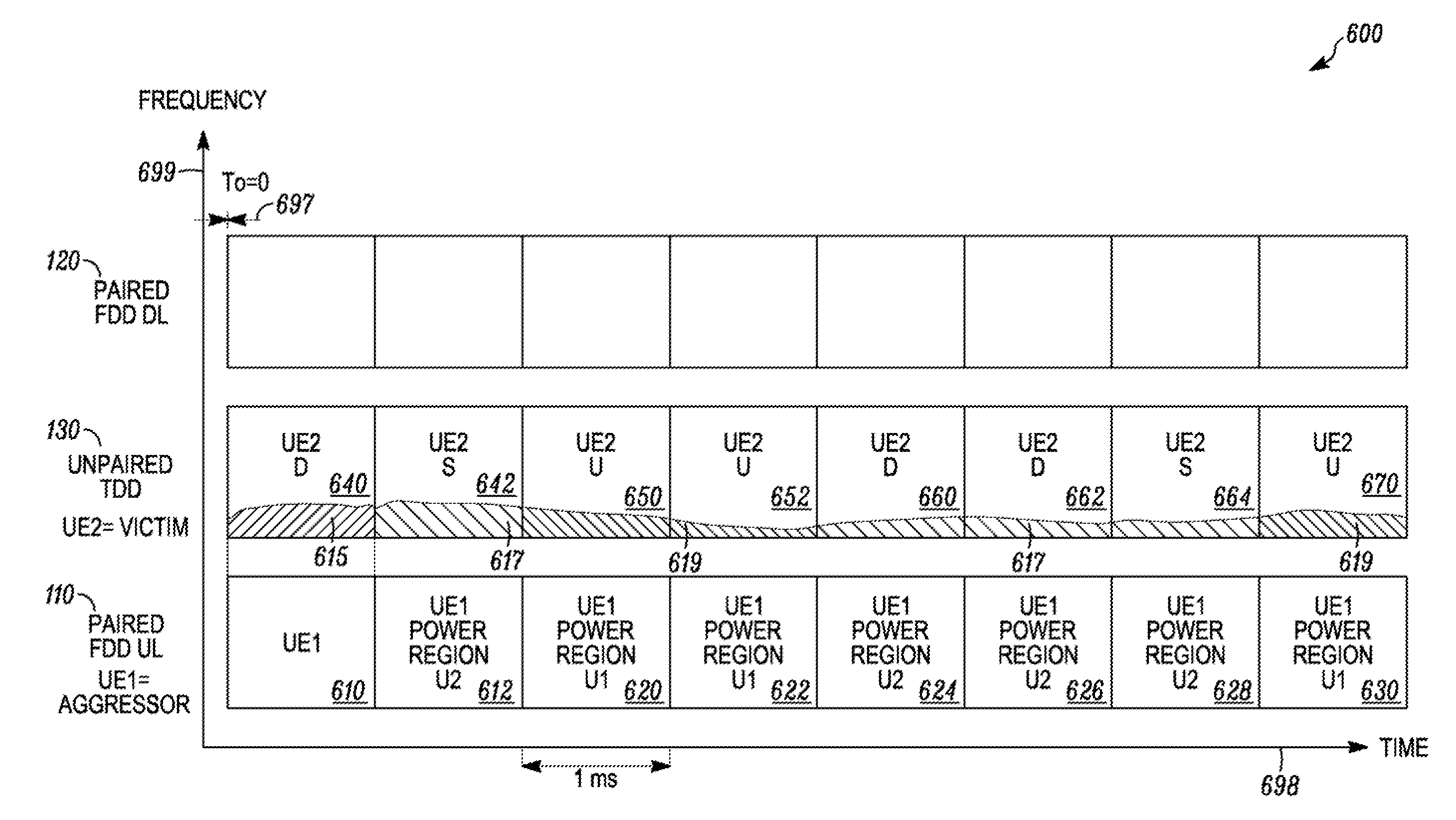
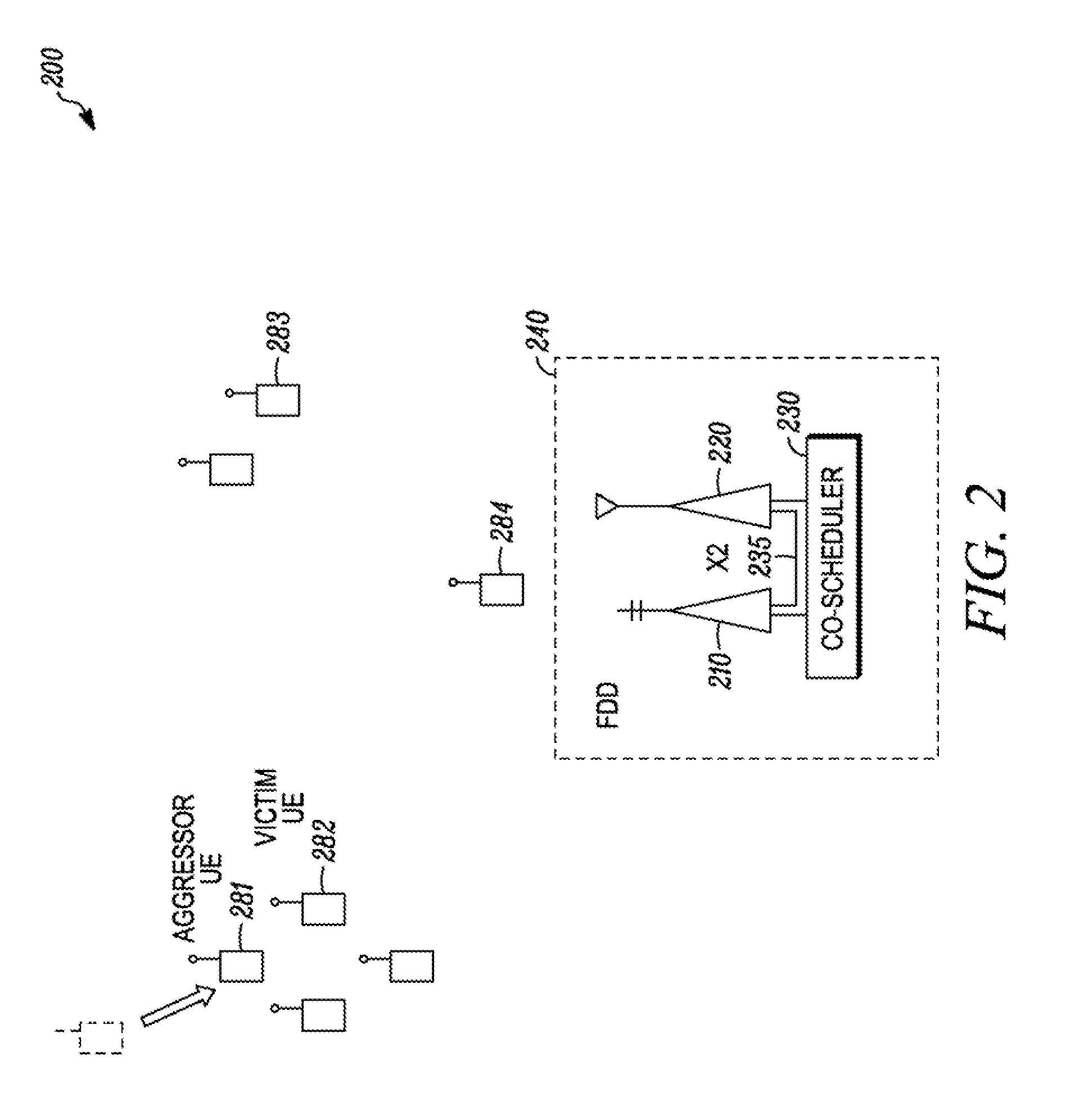
[0026]A wide variety of mechanisms can result in adjacent carrier system interference. Implementation of a method and apparatus for multi-radio coexistence allows a co-scheduler to arrange uplink and downlink subcarrier, subframe, and power assignments in adjacent carrier systems to mitigate interference by reducing the assignment of radio resources or transmission power on radio resources of proximal UEs on different networks that are projected to overlap in time and adjacent frequency. The different networks may also use different radio access technologies (RATs) such as LTE and HSPA, or LTE and GSM. The co-scheduler may specifically assign radio resources to each UE to reduce interference in a complete subframe or only a portion of a subframe. The co-scheduler may specifically attempt to reduce interference on a Physical Downlink Control Channel (PDCCH). The co-scheduler may specifically attempt to reduce interference during a proximal UE's channel measurement time period.

[0027]A...


PUM


Abstract

A method and apparatus for a co-scheduler can mitigate UE-to-UE adjacent carrier frequency band interference by allocating three sets to a first user equipment uplink. Each set has at least one sub-carrier in a first frequency band, at least one uplink time period, and at least one transmission power parameter. The co-scheduler initially allocates the first set. The co-scheduler allocates the second set in response to detecting a second user equipment operating proximal to the first user equipment, and the second set differs from the first set in either at least one sub-carrier or at least one transmission power parameter. The co-scheduler allocates the third set in response to detecting that the second user equipment is no longer operating proximal to the first user equipment, and the third set differs from the second set in either at least one sub-carrier or at least one transmission power parameter.

Description

FIELD OF THE DISCLOSURE[0001]This disclosure relates generally to improving coexistence among radios operating in adjacent frequency spectrum or bands. These radios may be collocated (i.e., within a single device) or non-collocated (i.e., not within a single device).BACKGROUND OF THE DISCLOSURE[0002]Coexistence refers to the ability for multiple wireless protocols to operate in or around the same or adjacent time-frequency radio resources without significant degradation to any radio's operation due to interference. Note that interference may occur at a reception radio frequency or at any intermediate frequency used within a receiving device for the purpose of demodulation. Without coexistence mechanisms, radio frequency interference can cause, amongst other degradations, loss of connectivity, decreased data throughput or reduction in quality of service, or increased current drain.[0003]When adjacent radio frequency bands are allocated to different uses, wireless interference can res...

Claims


Application Information

Patent Timeline
IPC IPC(8): H04W72/04H04W24/10
CPCH04L5/0035H04L5/0062H04L5/143H04W72/1268H04W92/20Y02B60/50H04W4/023H04W52/16H04W52/243H04W52/365H04W72/02H04W72/048H04W74/00H04W52/10Y02D30/70H04W72/51
Inventor FRANK, COLIN D.KRISHNAMURTHY, SANDEEP H.LOVE, ROBERT T.NIMBALKER, AJITNORY, RAVIKIRANSTEWART, KENNETH A.
Owner GOOGLE TECH HLDG LLC
Learn More