Heat pump system
Active Publication Date: 2012-10-18
DAIKIN IND LTD +1
View PDF7 Cites 12 Cited by
Summary
Abstract
Description
Claims
Application Information
AI Technical Summary
This helps you quickly interpret patents by identifying the three key elements:
Problems solved by technology
Method used
Benefits of technology
[0005]An object of the present invention is to make good efficiency operation possible in a heat pump system configured by connecting a plurality of usage units for performing an aqueous medium cooling or heating operation, and the heat pump system being capable of simultaneous cooling and heating operations, even under low outside air temperature and cooling and heating operations coexist conditions.
[0029]It is thereby possible to ensure that the heat-source-side refrigerant of the usage-side heat exchangers does not fall to a low temperature when cooling operation is not being performed, and freezing of the aqueous medium can be suppressed. A heat pump system according to a ninth aspect of the present invention is the heat pump system according to any of the first to eighth aspects of the present invention, wherein the heating operation is capable of heating the aqueous medium to 65° C. or higher.
Problems solved by technology
Accordingly, there is a problem in that the power consumption of the compressor is increased and the operating efficiency is reduced.
Therefore, there is a problem in that it is difficult to balance the heat load of the entire plurality of usage units by using a plurality of heat-source-side heat exchangers.
For this reason, the trend has been to increase the heat radiation capability of the heat-source-side heat exchangers that function as a refrigerant radiator, and the problem of reduced operating efficiency is more pronounced in the case that the outside temperature is low and cooling and heating operations coexist in a configuration that uses a usage unit having a usage-side heat exchanger for cooling and heating an aqueous medium.
Method used
Image
Click on the blue label to locate the original text in one second.
Reading with bidirectional positioning of images and text.
Examples
first embodiment
(1) First Embodiment
[0037]
[0038]—Overall Configuration—
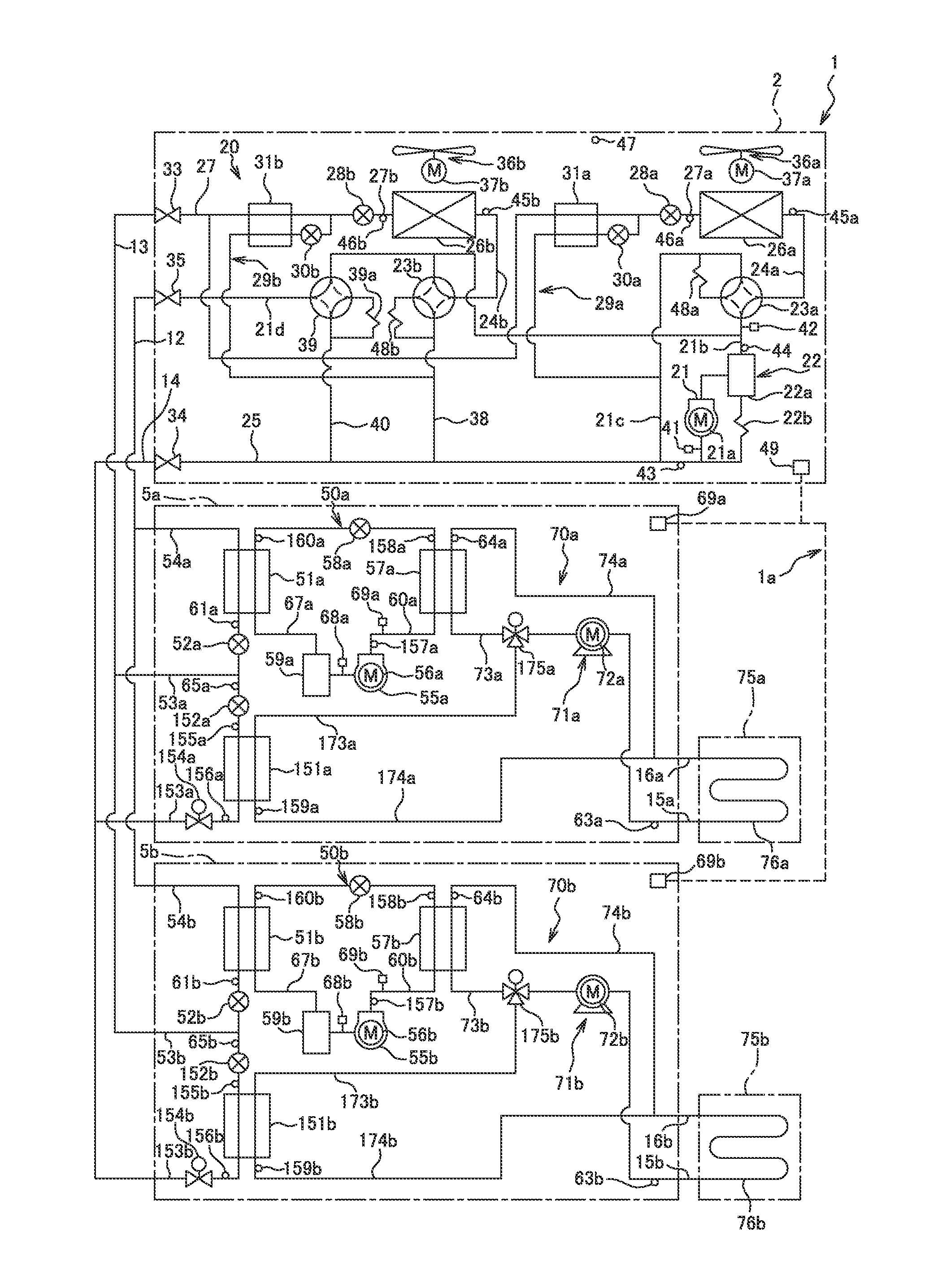
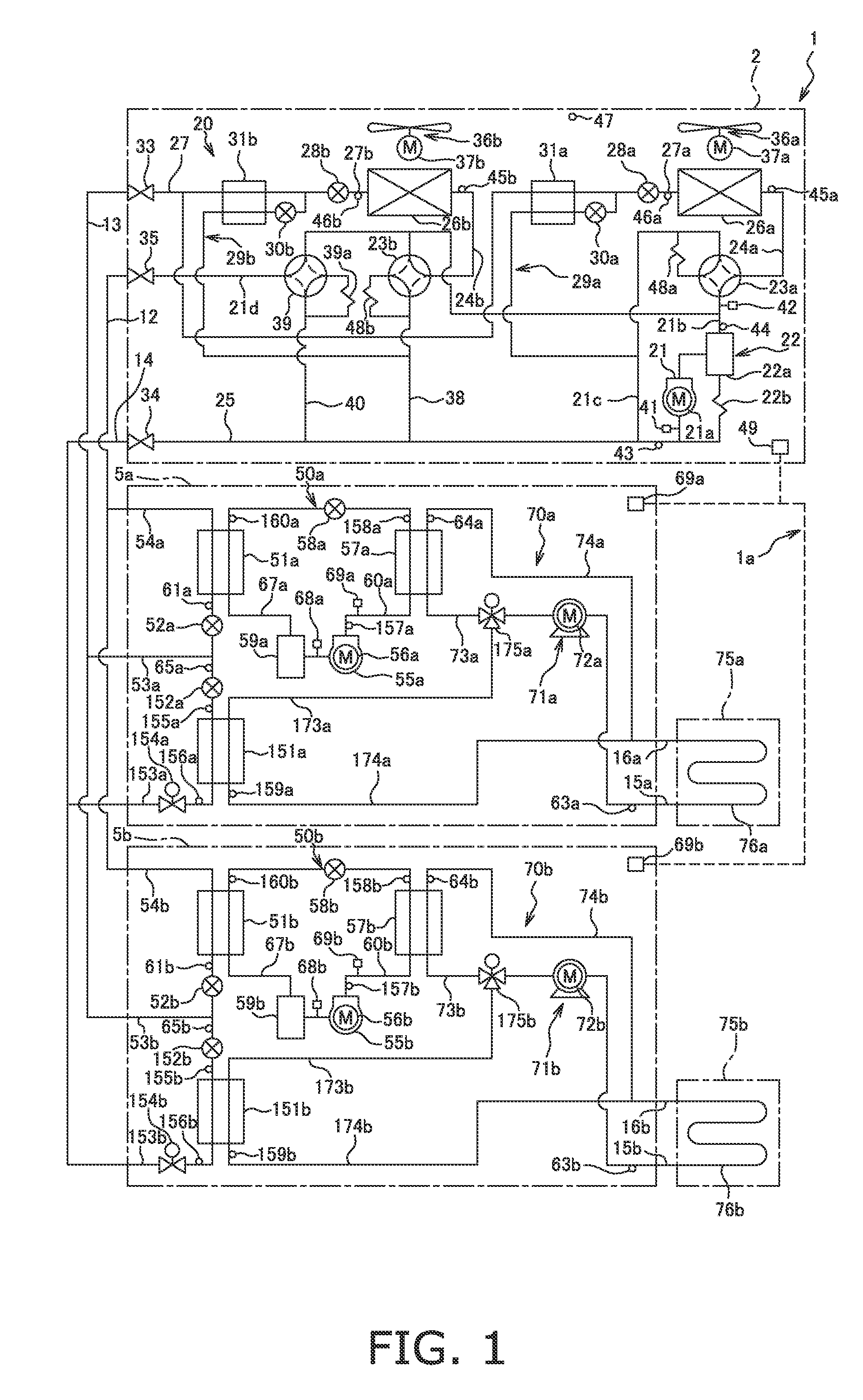
[0039]FIG. 1 is a schematic structural diagram of the heat pump system 1 according to the first embodiment of the present invention. The heat pump system 1 is an apparatus capable of an air-cooling operation (cooling operation) and an air-warming operation (heating operation) using a vapor compression heat pump cycle.
[0040]The heat pump system 1 mainly has a heat source unit 2, a plurality (two in FIG. 1) of usage units 5a, 5b, a discharge refrigerant communication tube 12, a liquid-refrigerant communication tube 13, an intake refrigerant communication tube 14, aqueous medium air-cooling / air-heating units 75a, 75b (aqueous medium usage apparatuses), and aqueous medium communication tubes 15a, 16a, 15b, 16b. The heat source unit 2 and usage units 5a, 5b are made into a heat-source-side refrigerant circuit 20 by being connected via the refrigerant communication tubes 12, 13, 14. The usage units 5a, 5b constitute usage-side refrige...
second embodiment
(2) Second Embodiment
[0176]
[0177]—Overall Configuration—
[0178]FIG. 4 is a schematic structural diagram of the heat pump system 101 according to the second embodiment of the present invention, The heat pump system 101 is an apparatus capable of performing an air-cooling operation (cooling operation), air-warming operation, and hot-water supply operation (heating operation) using a vapor compression heat pump cycle.
[0179]The heat pump system 101 mainly has a heat source unit 2, a plurality (two in FIG. 4) of usage units 105a, 105b, a discharge refrigerant communication tube 12, a liquid-refrigerant communication tube 13, an intake refrigerant communication tube 14, aqueous medium air-cooling / air-heating units 75a, 75b (aqueous medium usage apparatuses), and aqueous medium communication tubes 15a, 16a, 15b, 16b. The heat source unit 2 and usage units 105a, 105b are made into a heat-source-side refrigerant circuit 20 by being connected via the refrigerant communication tubes 12, 13, 14....
PUM
Abstract
A heat pumpsystem includes a heat-source-side refrigerant circuit and a controller. The heat-source-side refrigerant circuit has a plurality of usage units having usage-side heat exchangers. The plurality of usage units are connected to a heat source unit having a plurality of heat-source-side heat exchangers and a heat-source-side compressor configured to compress a heat-source-side refrigerant. The controller causes the plurality of heat-source-side heat exchangers to function as evaporators and radiators of heat-source-side refrigerant to perform an air-cooling operation and an air-warming operation using an aqueous medium. The heat pumpsystem operates so that the heat-source-side condensing temperature is below 40° C. in the case that an outside air temperature is 25° C. or lower and the cooling and heating operations coexist.
Description
TECHNICAL FIELD[0001]The present invention relates to a heat pumpsystem, and particularly relates to a heat pump system configured by connecting a plurality of usage units for performing an aqueous medium cooling or heating operation to a heat source unit having a plurality of heat-source-side heat exchangers, and the heat pump system being capable of simultaneous cooling and heating operations.BACKGROUND ART[0002]Patent Document 1 (Japanese Laid-open Patent Application No. 2006-343052) is a conventional air-conditioning apparatus. The air-conditioning apparatus (heat pump system.) has a plurality of indoor units (usage units) having an indoor heat exchanger (usage-side heat exchanger) that are connected to an outdoor unit (heat source unit) having a compressor, and first and second indoor heat exchangers (a plurality of heat-source-side heat exchangers), The heat pump system is capable of simultaneous air-cooling operation (cooling operation) and air-warming operation (heating ope...
Claims
Application Information
Patent Timeline
Application Date:The date an application was filed.
Publication Date:The date a patent or application was officially published.
First Publication Date:The earliest publication date of a patent with the same application number.
Issue Date:Publication date of the patent grant document.
PCT Entry Date:The Entry date of PCT National Phase.
Estimated Expiry Date:The statutory expiry date of a patent right according to the Patent Law, and it is the longest term of protection that the patent right can achieve without the termination of the patent right due to other reasons(Term extension factor has been taken into account ).
Invalid Date:Actual expiry date is based on effective date or publication date of legal transaction data of invalid patent.