Energy Recovery System and Method

a technology of energy recovery and energy storage, applied in the direction of lighting and heating apparatus, greenhouse gas reduction, instruments, etc., can solve the problems of wasting a large amount of heat by releasing hot gases, unable to transfer to steel, and finally dispersing into the atmospher

Active Publication Date: 2012-10-18
TMEIC
View PDF10 Cites 33 Cited by
  • Summary
  • Abstract
  • Description
  • Claims
  • Application Information

AI Technical Summary

Benefits of technology

[0006]The invention also relates to a method for regulating the generation of electrical power from heated waste gases emitted from a fuel-powered industrial device using the system described above. The optimum target temperature for the heat source liquid is calculated based on a function having as input variables the temperature feedback of heated gases entering the gas input of the heat exchanger and the device fuel consumption as indicated by the second controller, if such data is available, added to the heat source liquid initial target temperature. Then, a desired speed feed forward command for the first VFD is further calculated based on a function having as input variables the optimal heat source liquid temperature and a target speed reference for the second variable frequency drive. Yet a further calculation is then made of a speed adjustment for the exhaust gases fan based on the measured temperature of the heat source liquid and the proportional and integral gains of the Proportional-Integral regulator incorporated into the first controller. The target speed of the first VFD is then set along with its calculated maximum allowable speed. If the fan speed target exceeds the maximum allowable speed, it is clamped to the maximum allowable speed. Next, the target speed for the second VFD is subsequently calculated based on a function having as input variables the heat source liquid target temperature at the heat source liquid outlet of the heat exchanger and the temperature of the ORC system cooling fluid based on a feedback signal from a temperature sensor. The maximum allowable speed for the second VFD is determined based on a function having as an input variable the power output of the ORC as measured by the transducer. If the maximum allowable speed for the second VFD is exceeded, its target speed is clamped to the allowed level. Until the fuel-powered device is shut down, the method returns to the point where a determination is made whether fuel consumption data is available.

Problems solved by technology

The furnaces in general have a relatively low efficiency and an important portion of the heat produced as a result of the combustion of gas or other means, can't be transferred to the steel and is finally dissipated into the atmosphere.
Even though these systems normally recover a significant amount of heat, some significant portion of the heat is still wasted by releasing hot gases to the atmosphere.

Method used


Image

  • Energy Recovery System and Method
  • Energy Recovery System and Method
  • Energy Recovery System and Method

Examples


Embodiment Construction

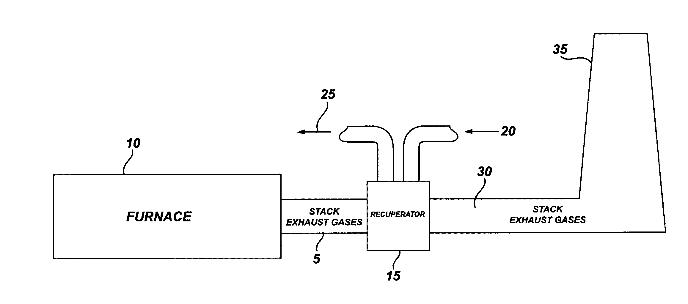
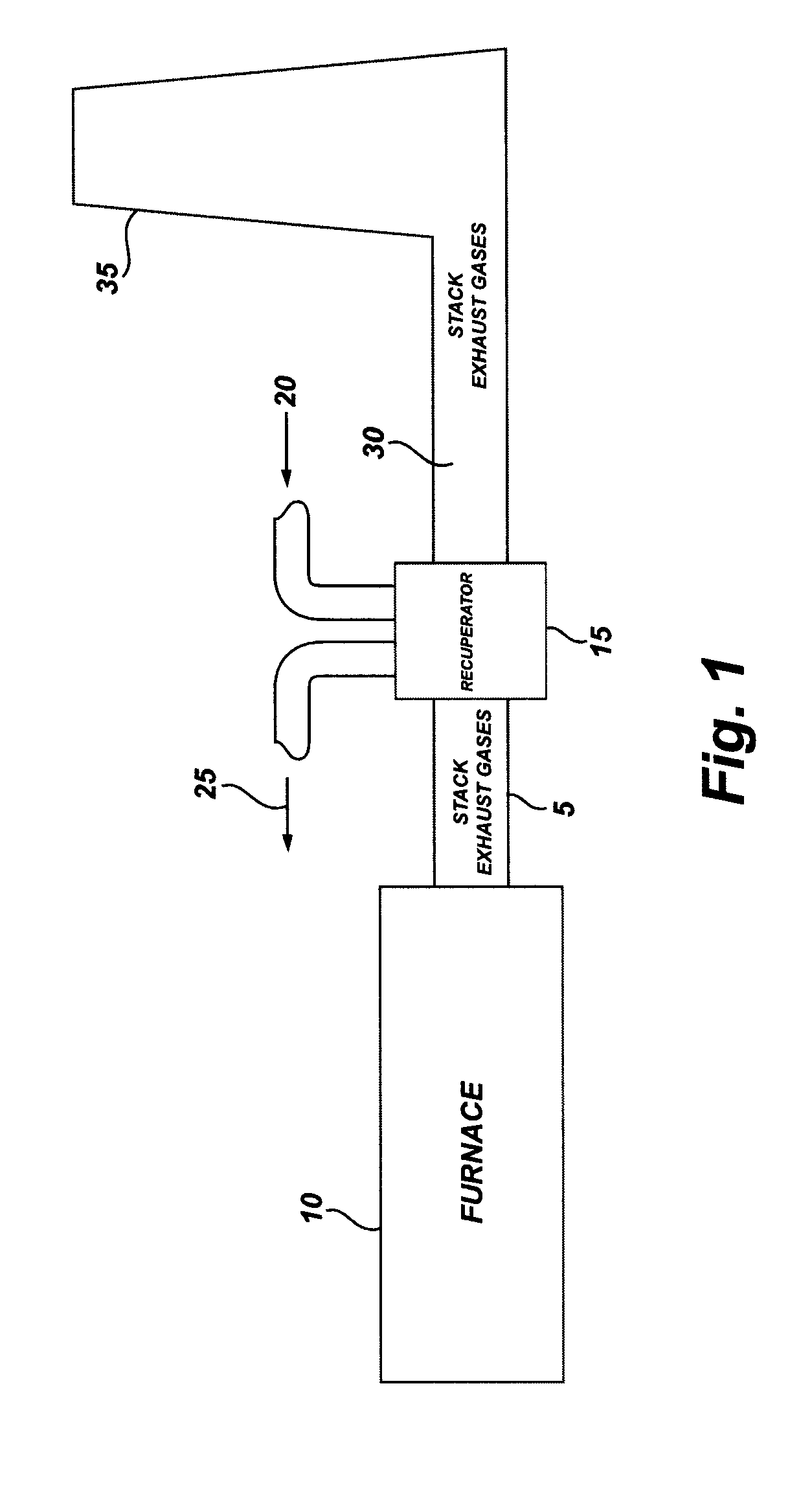
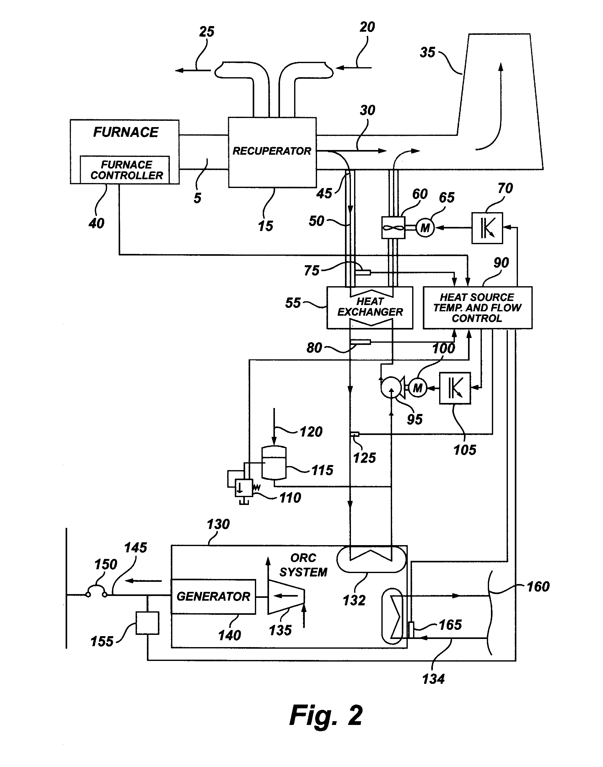
[0012]FIG. 2 illustrates in schematic diagram form the functional elements of the system of this invention. The same elements are present as shown in FIG. 1 but, in addition, furnace controller 40 is required to monitor the operation of furnace 10 and to provide data concerning furnace fuel consumption to controller 90, as discussed below. Tap 45 is added to divert at least a portion of the secondary exhaust gases 30 prior to their evacuation through an exhaust structure such as stack 35 into a tertiary exhaust gas stream 50. Tap 45 feeds tertiary exhaust gas stream 50 into first heat exchanger 55. This heat exchanger is designed based on the temperature range of the exhaust gases, the acceptable temperature range for the heat source liquid, the amount of heat to be transferred to the heat source liquid and the acceptable pressure drop on both circuits that will provide an economic solution based on the cost of the heat exchanger and the energy to be consumed by exhaust gases fan an...


PUM


Abstract

A system and method for converting otherwise wasted energy produced in the form of heated gases as a byproduct of an industrial process into electrical energy. At least some waste gases are diverted from a typical exhaust structure through a heat exchanger and back into the exhaust structure. The amount of gases flowing through the heat exchanger is monitored and regulated by a controller. A heat source liquid is simultaneously circulated under pressure through the heat exchanger and through an organic Rankine cycle system. The amount of heat source liquid being circulated is also monitored and regulated by the controller. The ORC system converts the heat from the heat source liquid into electricity.

Description

TECHNICAL FIELD[0001]The subject invention relates generally to an economical means for the conversion of otherwise wasted heat energy produced by industrial furnaces into electrical energy. More particularly, a system and method are disclosed for increasing the efficiency of a steel mill plant by recovering part of the wasted heat energy and transforming it into electrical energy that can be reused inside the same plant.BACKGROUND OF THE INVENTION[0002]Steel mills incorporate different types of furnaces. Slab reheating furnaces, annealing furnaces and other type of furnaces are typical in steel mill plants. The furnaces in general have a relatively low efficiency and an important portion of the heat produced as a result of the combustion of gas or other means, can't be transferred to the steel and is finally dissipated into the atmosphere.[0003]Steel mills are major consumers of electrical energy. Most of the power plants in the world use fossil fuels that generate CO2 emissions. T...

Claims


Application Information

Patent Timeline
Patent Type & Authority Applications(United States)
IPC IPC(8): F28F27/00G05D23/00F28D15/00
CPCF01K13/02Y02E20/363F23J15/06F01K25/08Y02E20/30F01K23/10Y02B30/70
Inventor DURMAZ, AHMETLARA, MARCELO ANDRES
Owner TMEIC
Why Eureka
Try Eureka