Light-emitting device, display device, light-emitting system, and display system

a technology of display device and light-emitting system, which is applied in the direction of static indicating device, organic semiconductor device, instrument, etc., can solve the problems of limiting layout flexibility, electric shock when the exposed electrode is touched, and electric leakage, etc., to achieve convenient and stable supply of power, high layout flexibility, and easy disassembly and assembly

Inactive Publication Date: 2012-10-18
SEMICON ENERGY LAB CO LTD
View PDF12 Cites 22 Cited by
  • Summary
  • Abstract
  • Description
  • Claims
  • Application Information

AI Technical Summary

Benefits of technology

[0036]The display device according to one embodiment of the present invention can also be attached to the surface of a wall; thus, a display system with extremely high layout flexibility can be formed. Further, a soft magnetic material is used for the power receiving electrode, so that a display system which can be easily detached and attached by magnetic force and can supply power stably can be formed.
[0037]According to one embodiment of the present invention, a highly reliable light-emitting device can be provided. Further, a lighting device or a display device with a high level of safety and without an exposed electrode can be provided. Furthermore, a lighting device or a display device with high layout flexibility can be provided. In addition, a light-emitting system or a display system to which the light-emitting device or the display device can be applied can be provided.

Problems solved by technology

This might result in electric shock when the exposed electrode is touched.
In addition, when water or the like is adhered to the exposed electrode, electric leakage might occur.
Further, when the light-emitting device is provide on a wall, a ceiling, or the like, the light-emitting device needs to be connected to a connection portion provided for the wall, the ceiling, or the like in advance, which limits layout flexibility.
Similarly, at least a wiring with an exposed electrode for supplying power is necessarily provided in a display device including an organic EL element; thus, troubles such as a short circuit, and disconnection due to mechanical stress on the wiring, and electric shock and electric leakage might occur.
In addition, when the display device is attached to a wall or the like, the display device cannot be laid out freely because the wiring is drawn out, which causes inconvenience.
However, in that case, when the surfaces of the coils on the transmitting side and the receiving side placed to face each other are relatively misaligned, power transfer efficiency is significantly reduced.
Accordingly, the relative position of a power transmitting device and a power receiving device included in a device employing such an electromagnetic induction method for transmitting power is limited, which limits layout flexibility.

Method used


Image

  • Light-emitting device, display device, light-emitting system, and display system
  • Light-emitting device, display device, light-emitting system, and display system
  • Light-emitting device, display device, light-emitting system, and display system

Examples


embodiment 1

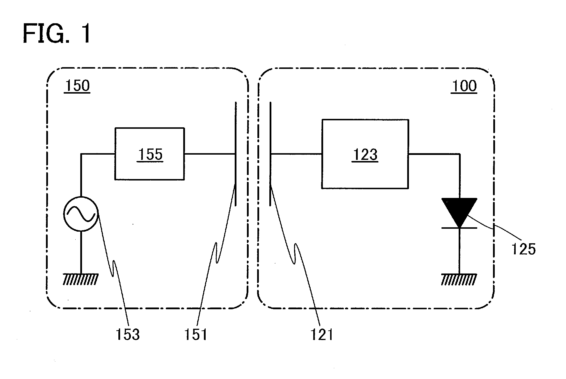
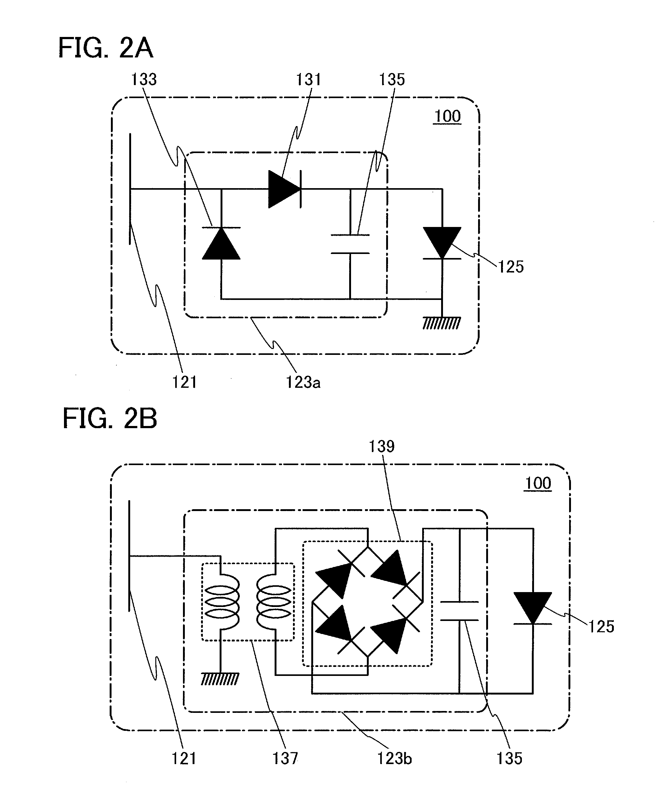
[0058]In this embodiment, a structural example of a light-emitting device in which a power transmission / reception method using electric field coupling is employed according to one embodiment of the present invention will be described with reference to FIG. 1 and FIGS. 2A and 2B.

[0059]FIG. 1 illustrates an example of structures of a light-emitting device 100 according to one embodiment of the present invention and a power transmitting device 150. The light-emitting device 100 includes a power receiving electrode 121, a rectifier circuit 123, and a light-emitting element 125.

[0060]The power transmitting device 150 transmits power to the light-emitting device 100 using electric field coupling. The power transmitting device 150 includes a power transmitting electrode 151, a high-frequency power source 153, and a matching circuit155.

[0061]As illustrated in FIG. 1, the power transmitting electrode 151 of the power transmitting device 150 is provided so as to face the power receiving elect...

embodiment 2

[0076]In this embodiment, specific structural examples of a light-emitting device in which a power transmission / reception method using electric field coupling is employed according to one embodiment of the present invention will be described with reference to FIGS. 3A and 3B, FIGS. 4A and 4B, FIGS. 5A and 5B, and FIGS. 6A and 6B.

example 1

Structural Example 1

[0077]FIG. 3A is a schematic top view of a light-emitting device 200 according to one embodiment of the present invention. FIG. 3B is a schematic cross-sectional view taken along line A-A′ in FIG. 3A. The light-emitting device 200 is a top-emission light-emitting device in which light is emitted to a counter substrate 211 side. The counter substrate 211 faces a substrate 201 over which a light-emitting element is provided.

[0078]The light-emitting device 200 includes a light-emitting element in which a lower electrode layer 103, an EL layer 105, and an upper electrode layer 107 are stacked, over the substrate 201 over which an insulating layer 217 and an insulating layer 219 are formed. When voltage is applied between the lower electrode layer 103 and the upper electrode layer 107, light emission from the EL layer 105 can be obtained.

[0079]Further, wirings 209a, 209b, and 209c are formed over the insulating layer 217.

[0080]The light-emitting device 200 has conduct...


PUM


Abstract

A highly reliable light-emitting device is provided. A lighting device or a display device with a high level of safety and without an exposed electrode is provided. A lighting device or a display device with high layout flexibility is provided. A light-emitting system or a display system to which the light-emitting device or the display device can be applied is provided. An electrode for receiving power and a rectifier circuit are provided in a light-emitting device including an organic EL element and arranged so as to face an electrode for transmitting power, whereby alternating-current power is supplied to the light-emitting device. The alternating-current power is rectified by the rectifier circuit to direct-current power so that the organic EL element in the light-emitting device is driven.

Description

BACKGROUND OF THE INVENTION[0001]1. Field of the Invention[0002]The present invention relates to a light-emitting device including an organic EL element. The present invention also relates to a display device including an organic EL element. The present invention also relates to a light-emitting system including the light-emitting device. The present invention also relates to a display system including the display device.[0003]2. Description of the Related Art[0004]An organic EL element has been actively researched and developed. In the fundamental structure of the organic EL element, a layer containing a light-emitting organic compound is provided between a pair of electrodes. By voltage application to this element, light emission from the light-emitting organic compound can be obtained.[0005]The organic EL element can be formed into a film shape; thus, a large-area element can easily be formed. Accordingly, the organic EL element has a high utility value as a surface light source ...

Claims


Application Information

Patent Timeline
Patent Type & Authority Applications(United States)
IPC IPC(8): H05B37/00G06F3/038H05B33/06H05B44/00
CPCH01L27/3244H05B33/0896H05B33/0815H01L2251/5361H05B45/60Y02B20/30H05B45/3725H10K59/12
Inventor KAMATA, KOICHIROSHIONOIRI, YUTAKAYAMAZAKI, SHUNPEI
Owner SEMICON ENERGY LAB CO LTD
Why Eureka
Try Eureka