

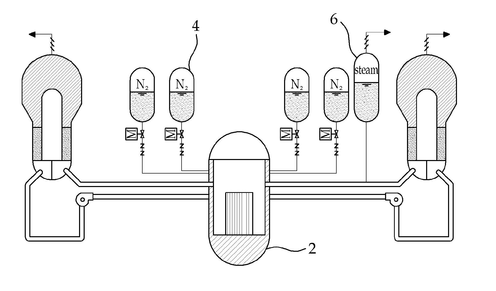
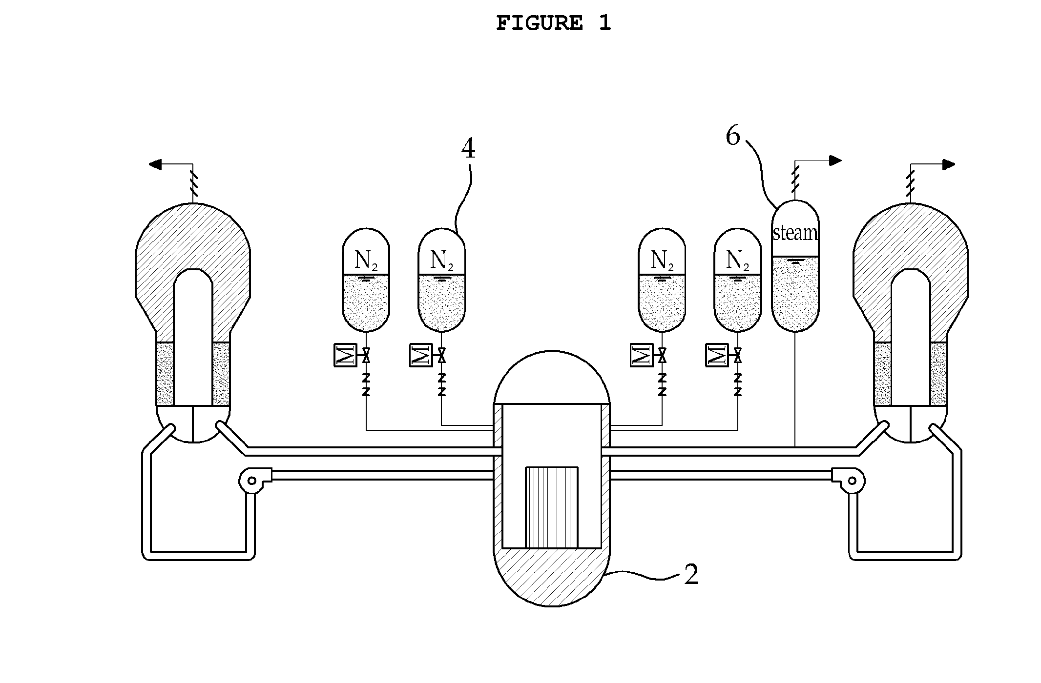
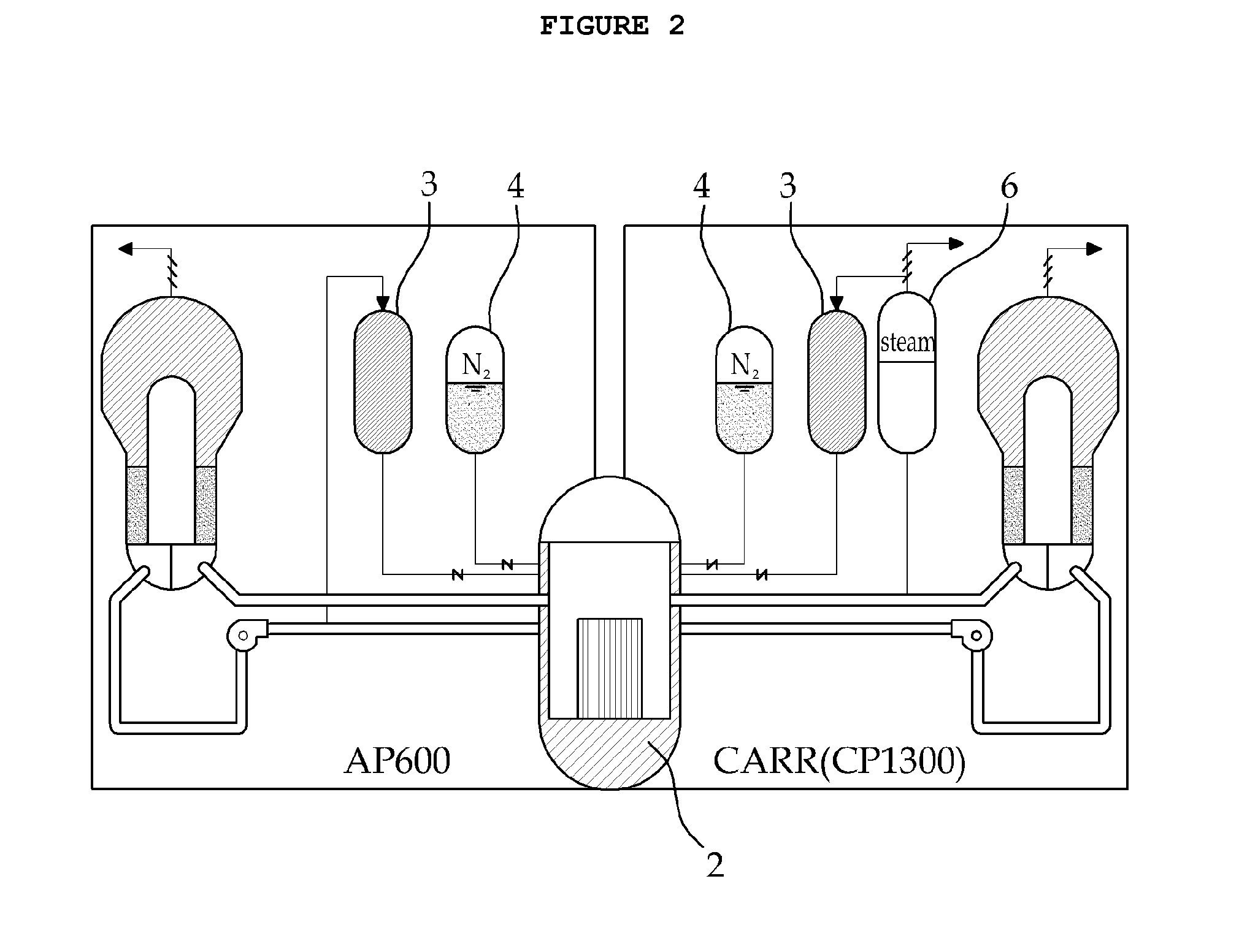
Passive high pressure safety injection tank system (HPSIT) for responding to station blackout (SBO) and loss-of-coolant accidents (LOCA)
a technology of high pressure safety injection and core cooling system, which is applied in the direction of nuclear engineering, nuclear elements, greenhouse gas reduction, etc., to achieve the effect of reducing the possibility of reactor accidents, simplifying system design, and simplifying emergency mitigation
- Summary
- Abstract
- Description
- Claims
- Application Information
AI Technical Summary
Benefits of technology
Problems solved by technology
Method used
Image

Examples
Embodiment Construction
[0044]Features and advantages of the present invention will be more clearly understood by the following detailed description of the present preferred embodiments by reference to the accompanying drawings. It is first noted that terms or words used herein should be construed as meanings or concepts corresponding with the technical spirit of the present invention, based on the principle that the inventors can appropriately define the concepts of the terms to best describe their own invention. Also, it should be understood that detailed descriptions of well-known functions and structures related to the present invention will be omitted so as not to unnecessarily obscure the important point of the present invention.
[0045]In one embodiment, one single safety injection tank (SIT), capable of shifting to high pressure condition, is provided as a replacement for the core makeup tank (CMT) and low pressure SIT, according to which it is possible to inject emergency core coolant to nuclear rea...
PUM
 Abstract
Description
Claims
Application Information