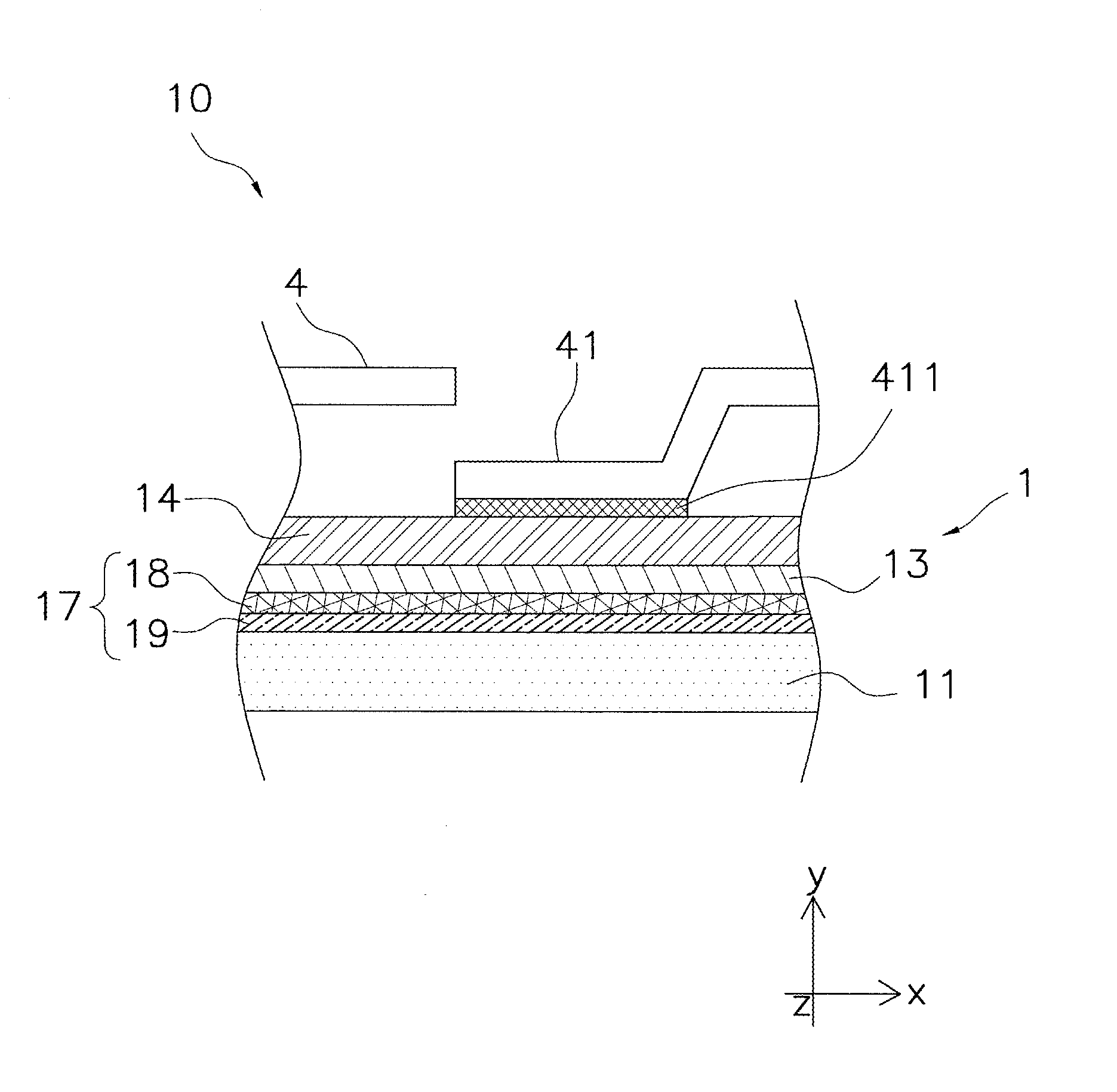
Fuel cell

a fuel cell and cell technology, applied in the field of fuel cells, to achieve the effect of enhancing the upper limi

Active Publication Date: 2012-10-18
NGK INSULATORS LTD
View PDF0 Cites 0 Cited by
  • Summary
  • Abstract
  • Description
  • Claims
  • Application Information

AI Technical Summary

Benefits of technology

[0008]The present invention enhances the uppe

Problems solved by technology

In recent years, fuel cell stack have attracted attention due t

Method used


Image

  • Fuel cell
  • Fuel cell
  • Fuel cell

Examples


examples

A Evaluation of Current-Voltage Characteristics of Cell

(1) Method

[0077]a. Preparation of Test Sample

a.-1. Formation of Anode

[0078]An anode is formed by the stacking formation described above. In other words, a ceramic green sheet (thickness 100 μm) configured from nickel oxide (NiO), zirconia (8YSZ), and PMMA as a pore-forming agent is stacked to 300 μm, and subjected to thermo compression bonding (60 degrees C., 3 MPa).

[0079]A ceramic green sheet formed from zirconia (8YSZ) that is separately prepared and a ceramic green sheet formed from ceria (GDC) are stacked in sequence onto the green body formed as described above, and subjected to thermo compression bonding.

[0080]In this manner, a stacked body in which the anode, zirconia layer, and ceria layer are stacked in sequence is co-fired for two hours at 1300-1500 degrees C.

[0081]Thereafter, an LSCF film (30 μm) is applied as a cathode onto the ceria layer and fired for two hours at 1000-1150 degrees C.

b. Evaluation of Cell Sample

[00...


PUM


Abstract

A fuel cell (1) includes an anode (11), a cathode (14), an electrolyte layer (13) containing ceria and provided between the anode (11) and the cathode (14), and at least two intermediate layers containing zirconia and provided between the electrolyte layer (13) and the anode (11). The at least two intermediate layers include a first intermediate layer (18) that contains ceria and a second intermediate layer (19) that has a higher zirconia concentration than the first intermediate layer and is provided between the first intermediate layer and the anode.

Description

TECHNICAL FIELD[0001]The present invention relates to a fuel cell, and more particularly relates to a solid oxide fuel cell.BACKGROUND ART[0002]In recent years, fuel cell stack have attracted attention due to efficient use of energy resources and environmental problems.[0003]Patent Literature 1 discloses a fuel cell stack that includes a solid electrolyte layer, an anode, and a cathode which disposed opposite to the anode with the solid electrolyte layer in-between as a reference. The solid electrolyte layer of this fuel cell employs a material formed by a solid solution of a rare earth metal in cerium oxide.CITATION LISTPatent Literature[0004][Patent Literature 1] Japanese Patent Application Laid-Open No. 2007-141492 (paragraph [0020] etc.)SUMMARY OF INVENTIONTechnical Problem[0005]However, a fuel cell using a ceria (i.e., cerium oxide) as electrolyte has problems that high-temperature operation is difficult, and durability is not sufficient. As a result, there is a need of improve...

Claims


Application Information

Patent Timeline
IPC IPC(8): H01M8/10
CPCH01M8/1213H01M8/126Y02E60/525H01M2300/0094Y02E60/521H01M2300/0074Y02E60/50Y02P70/50
Inventor KOBAYASHI, AYANOOHMORI, MAKOTO
Owner NGK INSULATORS LTD
Why Eureka
Try Eureka