

System and Method for Registration of Multiple Navigation Systems to a Common Coordinate Frame
a navigation system and coordinate frame technology, applied in the field of localization systems, can solve the problems of special sensors, inability to track the number of localization elements that can be simultaneously tracked, and inhomogeneities in electrical fields, so as to minimize the disadvantages, minimize the effect of inhomogeneities and dri
- Summary
- Abstract
- Description
- Claims
- Application Information
AI Technical Summary
Benefits of technology
Problems solved by technology
Method used
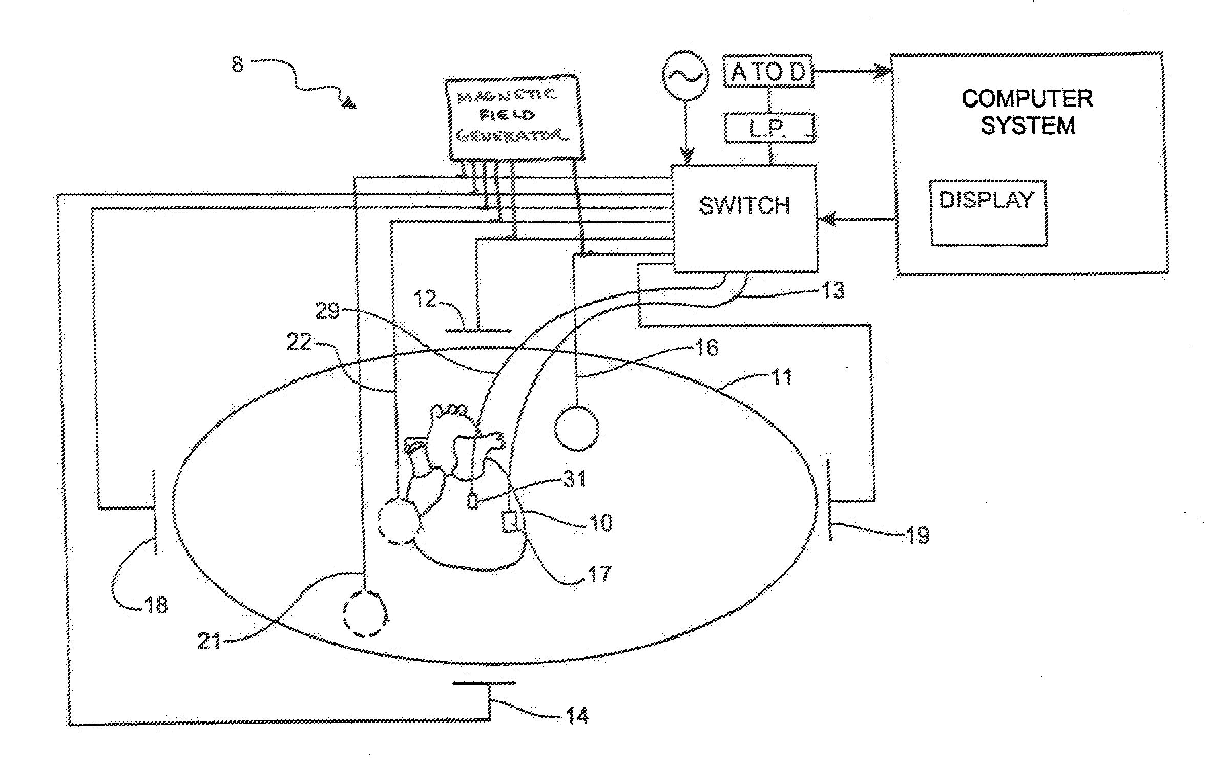
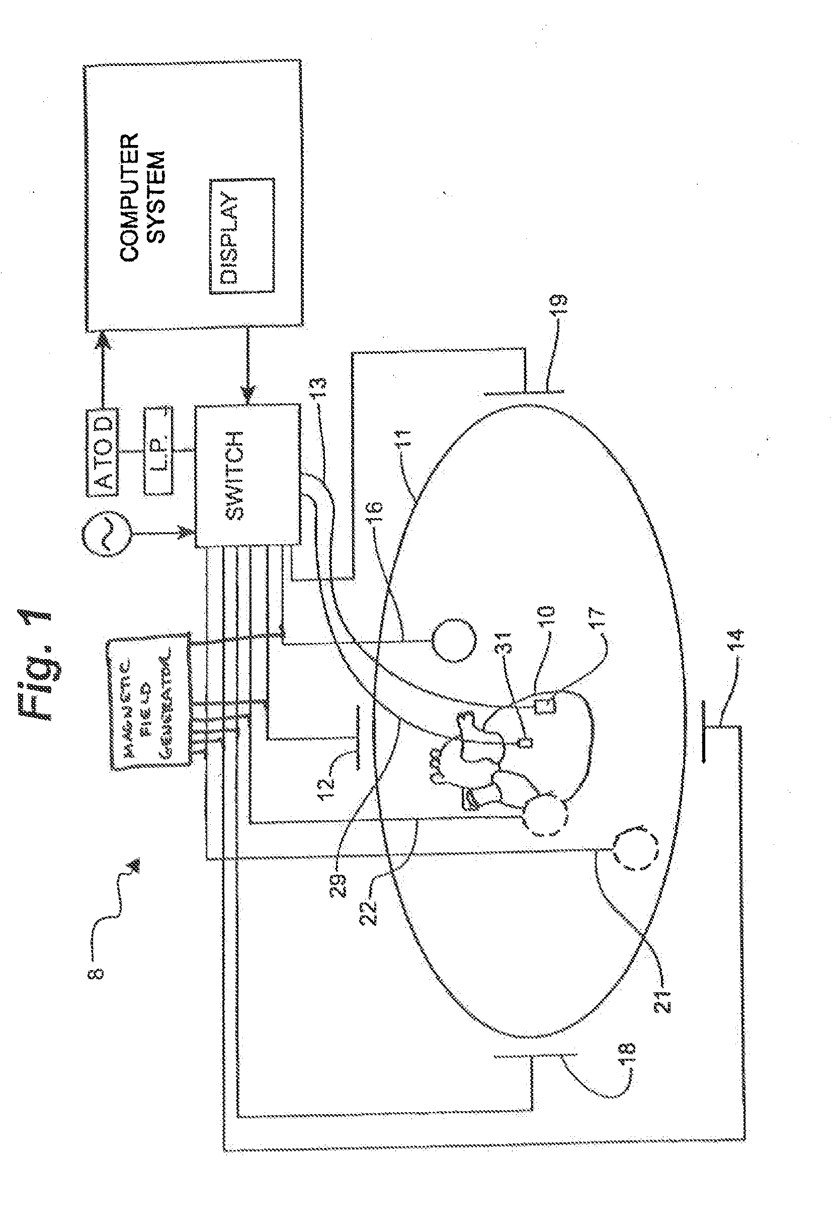
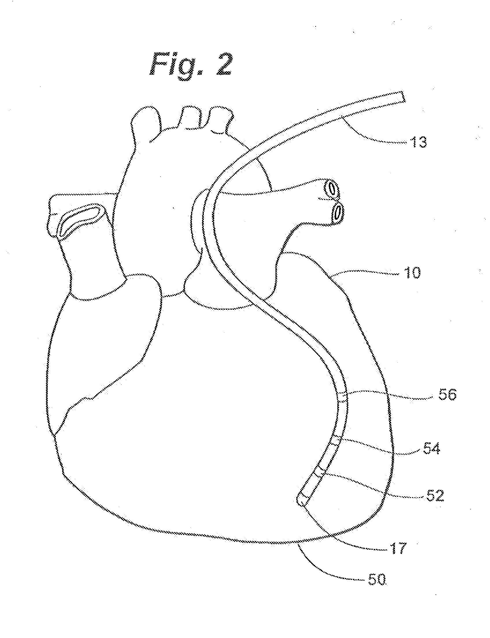
Image

Examples
case 1
[0069] No anomalies detected; operate as normal.
case 2
[0070] The impedance-based system has changed relative to the magnetic-based system, but there has been no change in the magnetic-based system. The anomaly is limited to the impedance-based system, and is likely drift (if it was dislodgement, Quantity B would also show a “Y”—see Case 4). The preferred mitigation is to compute an offset vector to account for this drift.
case 3
[0071] This is an unusual case, as the circumstances under which there would be a divergence in Quantity B but not Quantity C are very narrow (e.g., a dislodgement of the tertiary reference localization element and simultaneous, offsetting drift in the impedance-based localization system). The more likely explanation is that both systems have experienced an unknown anomaly, making navigation unreliable. Accordingly, the preferred mitigation is to compute a new mapping function fusing newly-collected fiducial groupings.
PUM
 Abstract
Description
Claims
Application Information