Coupling system to transfer material between containers

Inactive Publication Date: 2012-10-18
CHENG MARC BUNJIUN +2
View PDF13 Cites 82 Cited by
  • Summary
  • Abstract
  • Description
  • Claims
  • Application Information

AI Technical Summary

Benefits of technology

[0013]The exposed side of the stopper may have a central depressed area which receives a central tube of the male luer of the needleless syringe. The central depressed areas facilitates alignment of the male luer to the stopper. The depressed area may be sufficiently deep so as to define an inner surface frictionally engageable to an outer surface of the central nub so that the needleless syringe remains connected to the vial even when the vial is inverted and the syringe is released.
[0014]The flaps of the stopper may flex at bases. The flaps may engage a central tube of the needleless syringe to collectively provide a liquid tight seal with the central tube to prevent spillage of liquid medication in the vial and contamination of the liquid medication while extracting liquid from the vial.
[0015]The flaps may be fabricated from a resilient material to allow the flaps to quickly snap back to a closed configuration when the needleless syringe is removed from the stopper to mitigate spillage of liquid medication. More particularly, the stopper may be fabricated from a self closing material so that the liquid medication can be extracted from the vial with a needled syringe.
[0016]In another aspect, a method of extracting liquid medication from a vial i

Problems solved by technology

Unfortunately, the syringe has a sharp needle which is exposed while extracting fluid out of the vial.
As a result, the medical professional may be pricked with the exposed needle.
If the medical professional is pricked with the exposed needle prior to inj

Method used


Image

  • Coupling system to transfer material between containers
  • Coupling system to transfer material between containers
  • Coupling system to transfer material between containers

Examples


first embodiment

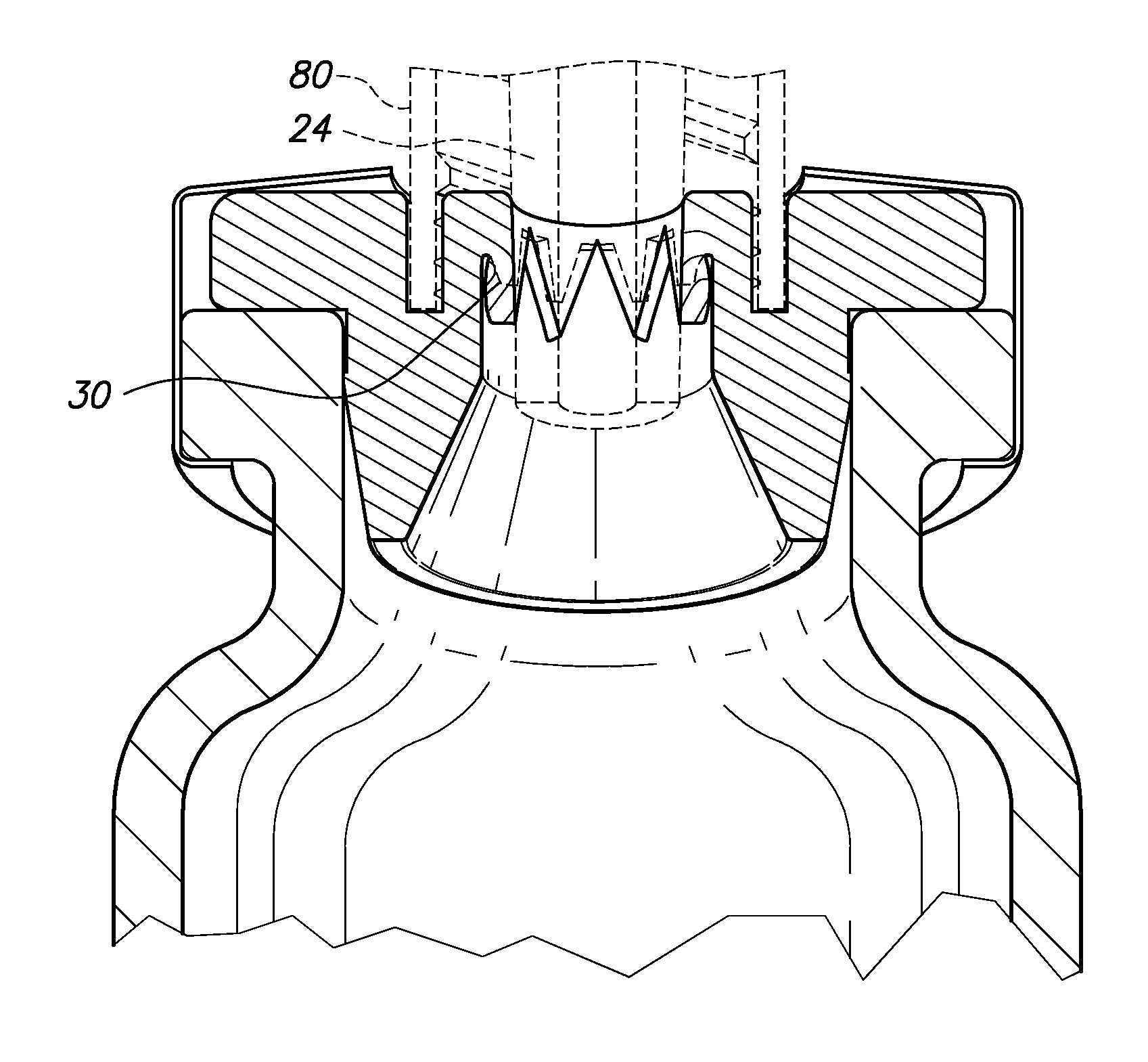
[0060]For the stopper 16 shown in FIG. 18, the elongate blunt portion 122 of the slip tip syringe 120 forms a liquid tight seal with the flaps 30. The fluid from the vial can be transferred to the slip tip syringe 120 without spillage of liquid medication within the container. Upon pull out of the elongate blunt portion 122 of the slip tip syringe 120 from the stopper 16, the flaps 30 spring back to the closed position and prevent spillage and contamination of the liquid medication within the vial.

second embodiment

[0061]For the stopper 16a shown in FIG. 19, the elongate blunt portion 122 of the slip tip syringe 120 forms a liquid tight seal with the flaps 30a. The fluid from the vial can be transferred to the slip tip syringe 120 without spillage of liquid medication within the container. Upon pull out of the elongate blunt portion 122 of the slip tip syringe 120 from the stopper 16a, the flaps 30a spring back to the closed position and prevent spillage and contamination of the liquid medication within the vial.

[0062]In both stoppers 16, 16a, the cylindrical groove 32, 32a are optional. As can be seen in FIGS. 18 and 19, the slip tip syringe 120 does not interact with the groove 32, 32a to form a liquid tight seal therebetween. Accordingly, it is contemplated that the stoppers 16, 16a may be fabricated without the cylindrical groove 32, 32a.

[0063]Referring now to FIG. 20, the stoppers 16, 16a either with or without the groove 32, 32a may be incorporated into an opening 202 of a container 200...


PUM


Abstract

A container containing liquid medication which can be accessed with a needleless syringe is disclosed. The vial includes a stopper defining a central portion. A blind side of the central portion of the stopper has a plurality of flaps defined by grooves. These grooves define weakened or attenuated areas that rupture when a central tube of a male luer of the needleless syringe pushes into the stopper. A liquid tight seal is formed between the male luer of the needleless syringe and the stopper to prevent spillage of liquid medication during the extraction process.

Description

CROSS-REFERENCE TO RELATED APPLICATIONS[0001]This application claims the benefits of U.S. Pat. App. Ser. No. 61 / 517,091, filed on Apr. 14, 2011, the entire contents of which are expressly incorporated herein by reference.STATEMENT RE: FEDERALLY SPONSORED RESEARCH / DEVELOPMENT[0002]Not ApplicableBACKGROUND[0003]The embodiments disclosed herein relate to a needleless syringe having a standard male luer tip syringe that access liquid medication within a container without the associated dangers of needle pricking.[0004]In the medical profession, liquid medication is administered to patients. Standard medical practice is to transfer the liquid medication from a vial into a syringe. The syringe is then used to inject the liquid medication into the patient. Unfortunately, the syringe has a sharp needle which is exposed while extracting fluid out of the vial. Also, the sharp needle of the syringe is exposed while administering the liquid medication to the patient. As a result, the medical pr...

Claims


Application Information

Patent Timeline
IPC IPC(8): A61J1/20
CPCA61J1/2096
Inventor CHENG, MARC BUNJIUNTIEN, ALBERT FUTSUCHENG, WEIBON WAYNE
Owner CHENG MARC BUNJIUN
Why Eureka
Try Eureka