
Surgical procedure for expanding a vertebral canal

a technology of vertebral canal and surgical method, which is applied in the field of surgical method for expanding a vertebral canal, can solve the problems of restricted mobility, significant increase in subsequent neck pain, and disadvantages, and achieve the effect of enabling the expansion of the vertebral canal and less stress for the patien

Active Publication Date: 2012-10-18
AESCULAP AG
View PDF9 Cites 10 Cited by
  • Summary
  • Abstract
  • Description
  • Claims
  • Application Information

AI Technical Summary

Benefits of technology

[0014]The object of the invention is to provide a method enabling expansion of the vertebral canal of vertebrae with less stress for the patient.

Problems solved by technology

In spite of the reduced surgical intervention in the bone substance in comparison with other dorsal methods, a significantly increased rate of subsequent neck pain is still regarded as a disadvantage of laminoplasty, as is restricted mobility of the cervical spine, which is often observed.

Method used


Image

  • Surgical procedure for expanding a vertebral canal
  • Surgical procedure for expanding a vertebral canal
  • Surgical procedure for expanding a vertebral canal

Examples


first embodiment

[0154]FIG. 13 shows a multiple implant 90 which is suited for insertion as one implant into incision gaps made in successive vertebrae. The shape of the multiple implant 90 corresponds substantially to the implant 80 in relation to the implant areas 92, 93, 94 or incision gaps provided per vertebra. The implanted state is shown schematically by way of example in a section of the cervical spine 10 in the plan view. As the implant areas are essentially fixedly connected to one another, they thus result in a stabilization and a certain immobilization of the treated section of the spine.

second embodiment

[0155]FIG. 14 shows a multiple implant 96 in which the individual implant sections 98, 99, 100 are not fixedly, but movably connected to one another. Such a connection may, in particular, be of articulated configuration and, further preferred, as shown in FIG. 14, of elastic configuration in the sagittal direction, for example, by means of helical springs 102. Here, too, stabilization of the treated section 10 of the spine occurs, but without the immobilization which in many cases is undesired.

[0156]A variant of the multiple implant 96 of FIG. 14 is shown in FIG. 15. The multiple implant 110 shown therein has instead of the helical springs 102 leaf springs 112, 113 for coupling the implant sections 114, 115, 116 to one another movably and resiliently.

[0157]A further variant of the multiple implant 96 of FIG. 14 is shown in FIG. 16. In this multiple implant 120, the elastic connection between the individual implant sections 122, 123, 124 is made by elastomer bridges 126, 127. The ela...


PUM


Abstract

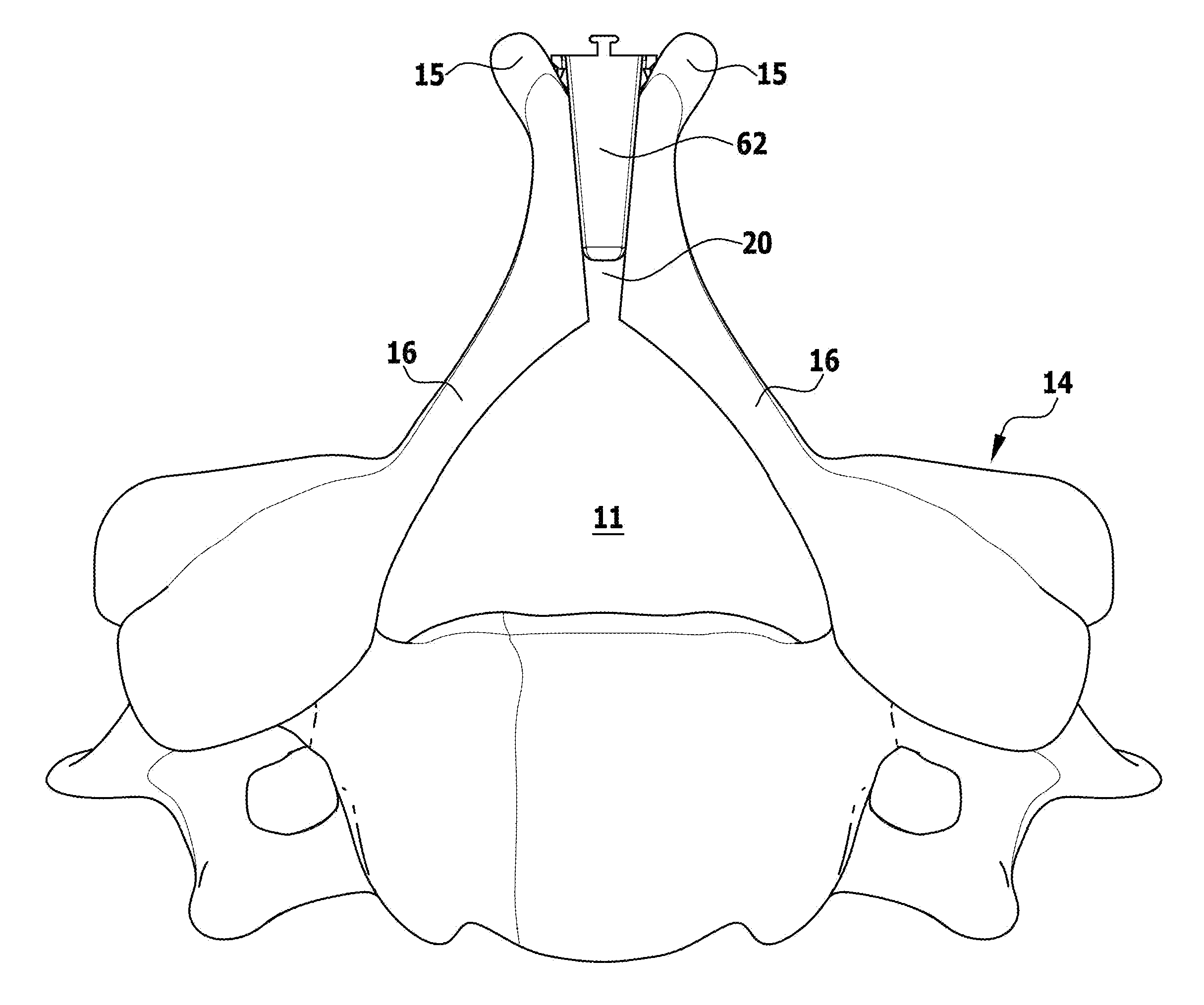
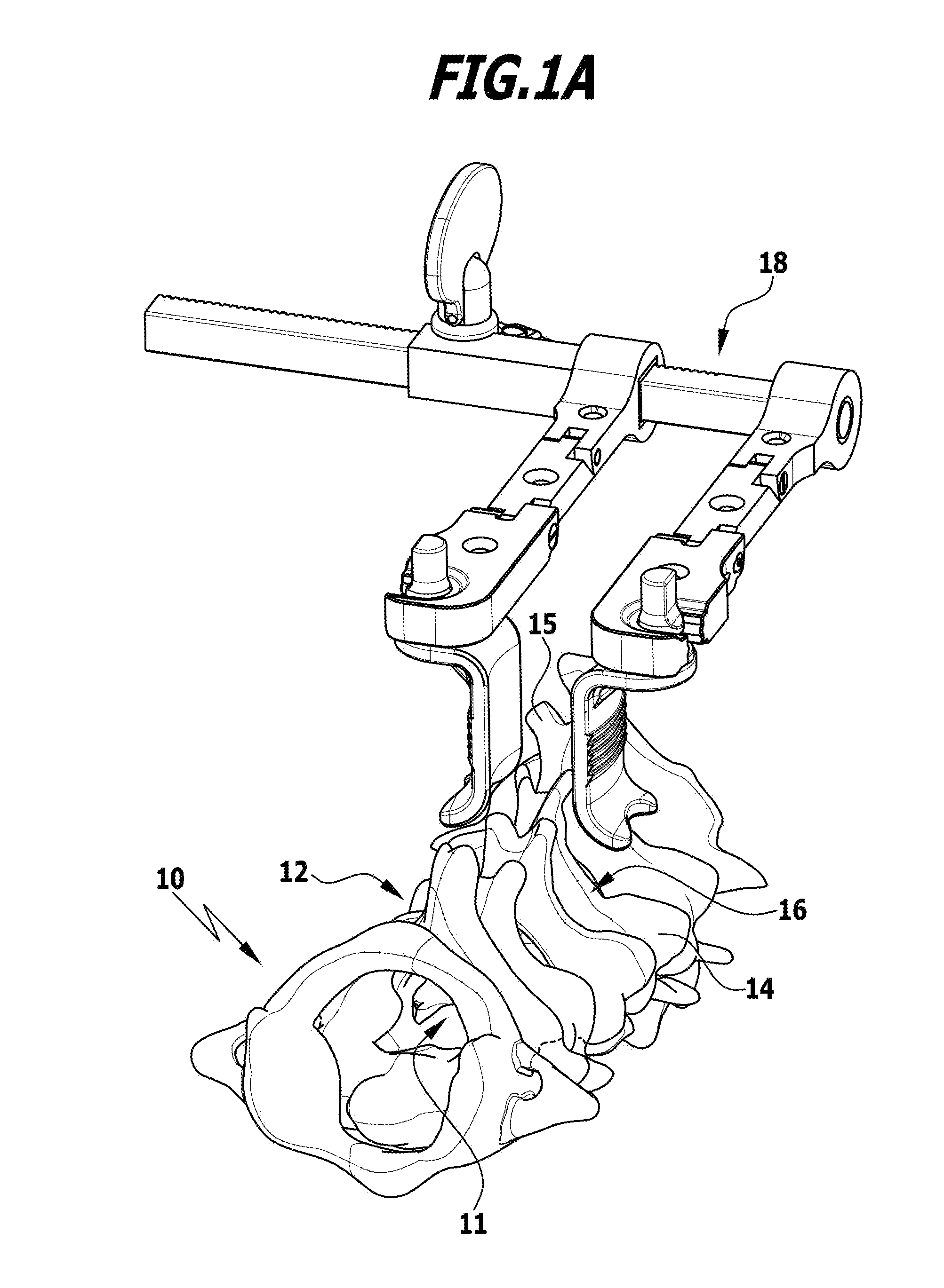
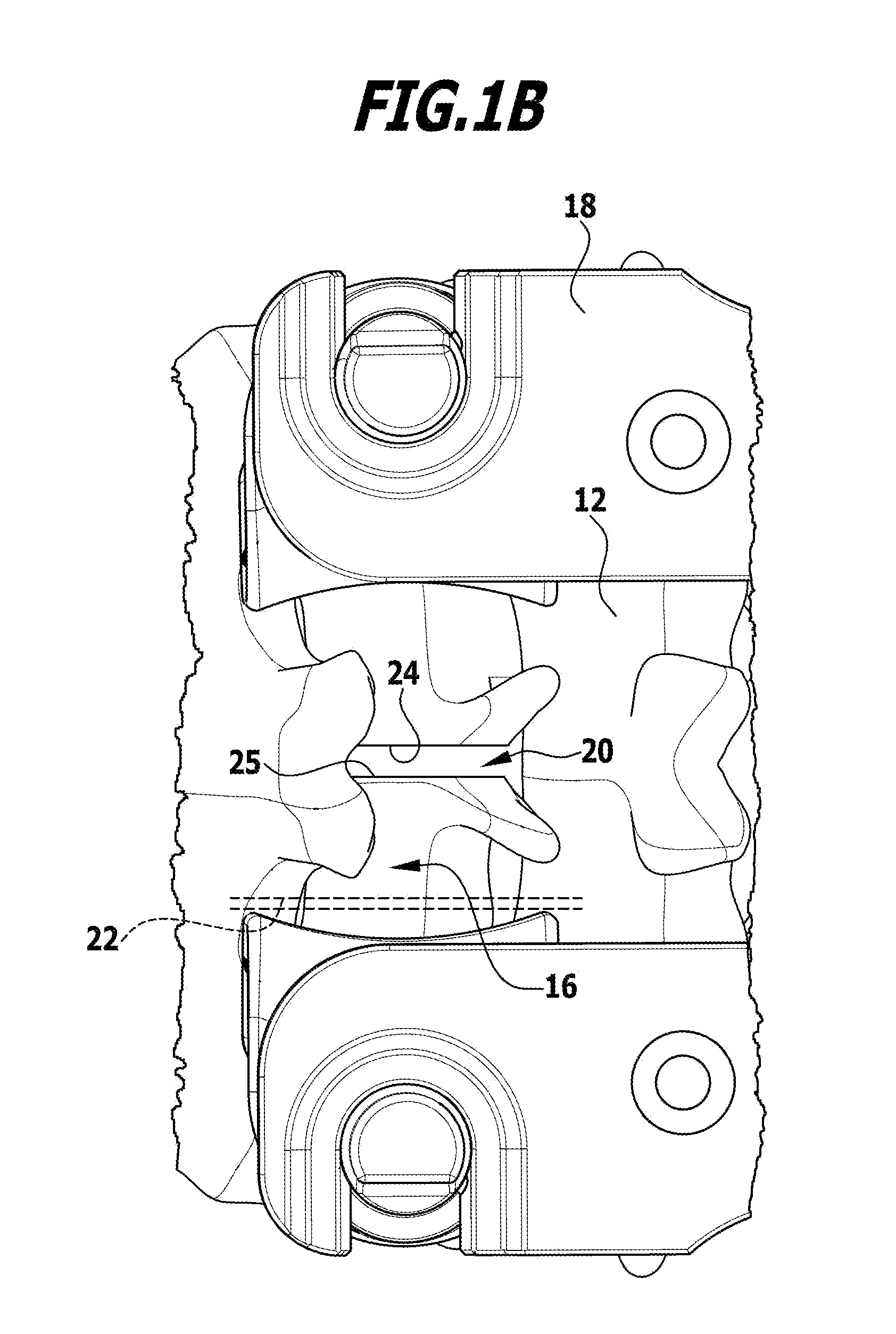
To provide a method with which expansion of the vertebral canal of vertebrae is possible with less stress for the patient than with the surgical methods used to date, it is proposed that herein the vertebral arch be split and an incision gap thereby be formed, and the incision gap bounded by opposed incision surfaces be expanded to a prescribed gap width and the bone substance of the resulting vertebral arch sections thereby be elastically / plastically deformed.

Description

[0001]This application claims the benefit of commonly-owned U.S. provisional application No. 61 / 474,393 filed on Apr. 12, 2011, which is incorporated herein and made a part hereof by reference.BACKGROUND OF THE INVENTION[0002]The invention relates to a surgical method for expanding a vertebral canal of a vertebra of the spine, also called laminoplasty.[0003]The vertebral canals of the vertebrae of the spine form the so-called canalis vertebralis or spinal canal in which the spinal cord, enclosed by the spinal meninx, is located.[0004]The spinal cord as part of the central nervous system may be prevented from functioning properly if, for example, with the occurrence of spinal canal stenosis, pressure is exerted on the spinal cord. This may have several causes, for example, the existence of spondylosis or ossification of the posterior longitudinal ligament.[0005]This may be remedied by enlargement of the vertebral canal of the vertebra or vertebrae of the spine that is or are affected...

Claims


Application Information

Patent Timeline
IPC IPC(8): A61F2/44A61B17/16
CPCA61B17/0206A61F2002/3093A61B17/025A61B17/1757A61B17/683A61B17/7071A61B17/86A61B17/8625A61B17/8866A61B2017/0256A61B2019/461A61B2019/464A61F2/44A61F2/4611A61F2002/30158A61F2002/30172A61F2002/30232A61F2002/30266A61F2002/30563A61F2002/30566A61F2002/30571A61F2002/30576A61F2002/30777A61F2002/30787A61F2002/30794A61F2002/30848A61F2002/30883A61B17/0293A61B2090/061A61B2090/064A61F2002/3079A61F2002/30845
Inventor BEGER, JENSLINKE, RALPHSUCHOMEL, PETRKLINGSEIS, SUSANNE
Owner AESCULAP AG
Learn More