Heat Retention and Insulation System for Wearable Articles

a technology of insulation system and wearable article, which is applied in the direction of thin material handling, clothing, footwear, etc., can solve the problems of reducing the lofted airspace, and reducing the radiation of heat loss. , to achieve the effect of reducing the conduction of body hea

Inactive Publication Date: 2012-10-25
KEEN INC
View PDF26 Cites 39 Cited by
  • Summary
  • Abstract
  • Description
  • Claims
  • Application Information

AI Technical Summary

Benefits of technology

[0003]However, in known cold-weather footwear, heat loss may occur through radiation and conduction of heat from the wearer's foot to the cold, exterior surfaces in contact with the footwear. For example, the outsole of the footwear may conduct heat to exterior surfaces of the footwear. In some examples, such exterior surfaces may be exposed to the elements and may be covered in ice and snow. In conventional cold-weather footwear, various insulating layers with lofted air may be used to attempt to reduce heat transfer. However, positioning lofted airspace in the insole and / or midsole in such footwear results in excessive compression due to the wearer's weight, thus decreasing the lofted airspace and effectively eliminating the insulating ability of such layers during wear.
[0005]The inventors herein recognize potential issues with the above vacuum configuration. As one example, vacuum sealing may degrade over time, and thus loss of the vacuum may result in loss of the insulating ability of the footwear. As another example, even if the vacuum is maintained over the life of the footwear, the lack of heat capacity of the vacuum layer reduces its ability to store heat. For example, even if radiated heat is reflected back into the foot space; the insulating layer as part of the vacuum cannot absorb and store the radiated heat. The inability to store radiated heat reduces the capability to maintain a warm internal space.
[0009]By providing a layered insulation pack with a lofted air space from the perforated layer, heated air may circulate throughout the inner body space of the footwear. Air retained in the footwear may be warmed by radiated body heat and retained within the perforated and insulating layers. Further, the reflective layer reflects the warmed air (the radiated body heat) back into the lofted air space and the inner body space, thus contributing to warming the wearer's foot. The retention of the warmed air in the lofted air space insulates the wearer from heat loss by reducing the conduction of body heat through the outsole to a cold exterior surface.

Problems solved by technology

However, in known cold-weather footwear, heat loss may occur through radiation and conduction of heat from the wearer's foot to the cold, exterior surfaces in contact with the footwear.
In some examples, such exterior surfaces may be exposed to the elements and may be covered in ice and snow.
However, positioning lofted airspace in the insole and / or midsole in such footwear results in excessive compression due to the wearer's weight, thus decreasing the lofted airspace and effectively eliminating the insulating ability of such layers during wear.
During use, heat radiation is impeded by the reflective layers and conduction is inhibited by the vacuum of the sealed enclosure body.
As one example, vacuum sealing may degrade over time, and thus loss of the vacuum may result in loss of the insulating ability of the footwear.
As another example, even if the vacuum is maintained over the life of the footwear, the lack of heat capacity of the vacuum layer reduces its ability to store heat.
For example, even if radiated heat is reflected back into the foot space; the insulating layer as part of the vacuum cannot absorb and store the radiated heat.
The inability to store radiated heat reduces the capability to maintain a warm internal space.
Further, the warm air in the lofted air space may act as an insulating layer, limiting conduction of body heat to a cold exterior environment.

Method used


Image

  • Heat Retention and Insulation System for Wearable Articles
  • Heat Retention and Insulation System for Wearable Articles
  • Heat Retention and Insulation System for Wearable Articles

Examples


Embodiment Construction

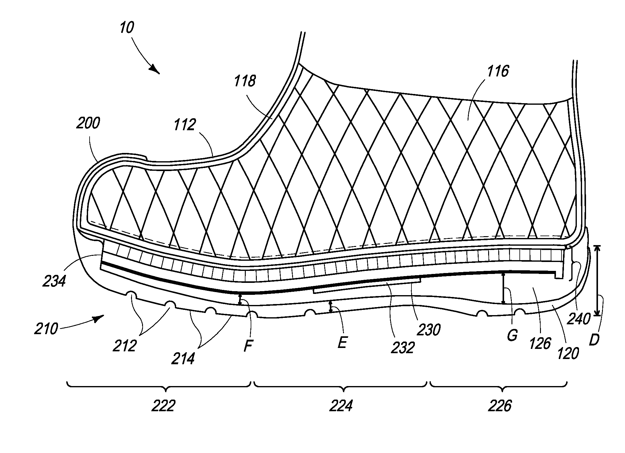
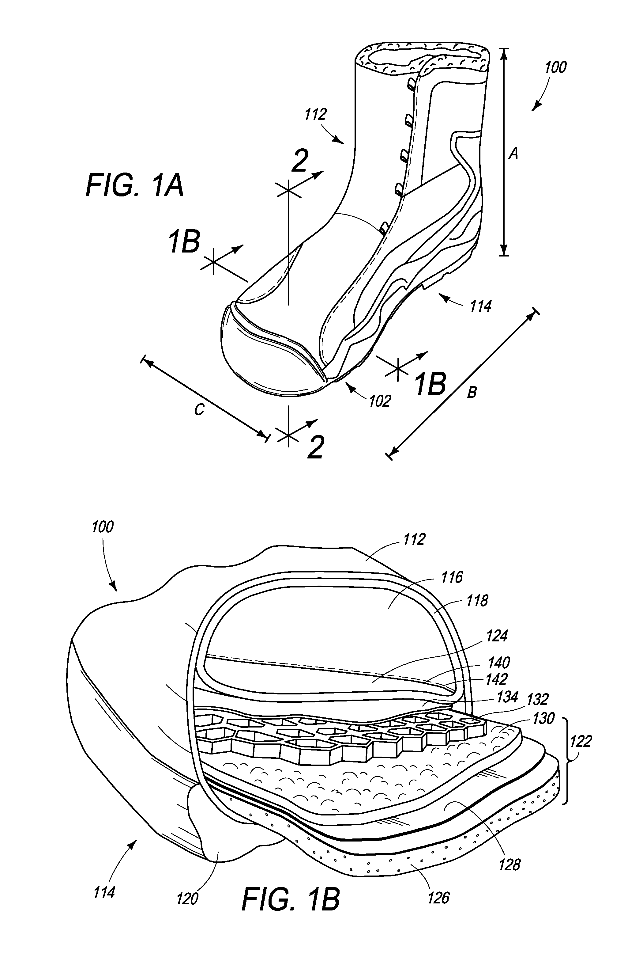
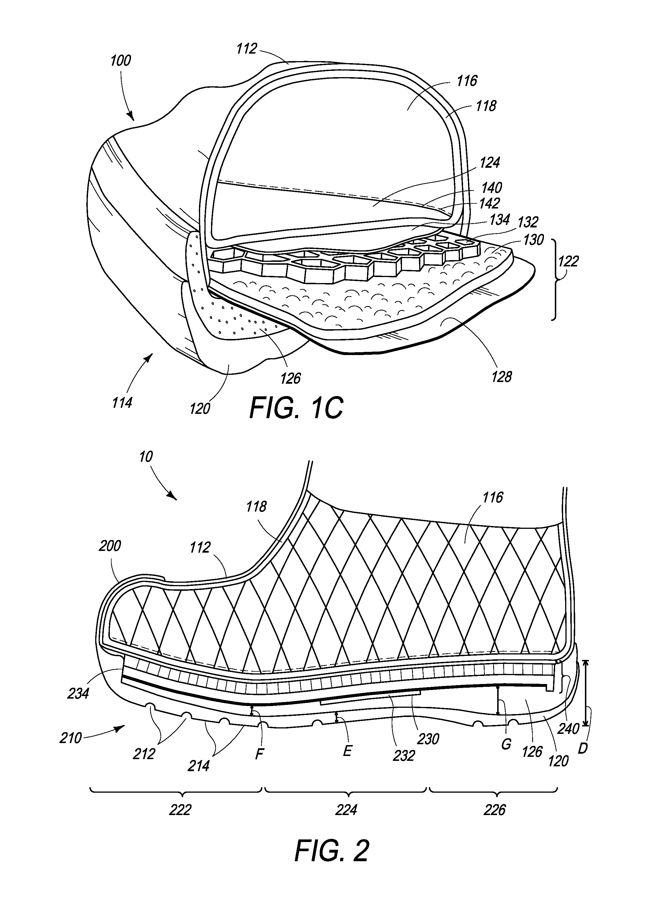
[0021]The following description relates to an insulation and warmth retention system for a wearable article or item. As described in more detail below, in one example, an insulation and warmth retention system may include a layered insulation pack. The layered insulation pack may include a perforated air communication and retention layer, also referred to as a perforated layer, a compressible layer and a reflective layer. The perforated layer may be disposed in the wearable article such that it is in air communication with an inner body space. A lofted air space may be formed from the perforated layer where heated air may circulate throughout the inner body space of the wearable article through the perforated layer. Air retained in the wearable article, such as for example, footwear, may be warmed by radiated body heat and retained within the perforated and insulating layers. Further, in some embodiments, the reflective layer may reflect the warmed air (the radiated body heat) back ...


PUM

PropertyMeasurementUnit
widthaaaaaaaaaa
depth/heightaaaaaaaaaa
heightaaaaaaaaaa

Abstract

The present application relates to an insulation pack in a wearable article, such as a footwear article. In one example embodiment, the insulation pack includes a perforated air retention and communication layer, an insulating compressible layer, and a reflective layer. In a compressed state, when the wearable article is worn by a wearer, the perforated air retention and communication layer and the insulating compressible layer maintain a lofted air space which is in air communication with an inner body space of the wearable article and acts as an insulating layer. Further, the reflective layer reflects radiated body heat. Thus, the insulation pack may provide a heat retention and insulation system for the wearable article by reducing body heat lost via radiation and conduction.

Description

FIELD[0001]The present application relates to an insulation pack for a wearable article, such as footwear.BACKGROUND AND SUMMARY[0002]The protective and insulating capabilities of wearable articles, including footwear, are important considerations depending on the intended use of such wearable articles. As an example, manufacturers have adapted footwear to perform based on potential outside conditions that the footwear is to be exposed to provide better comfort and protection for a user. For example, cold-weather footwear may be designed to retain or maintain heat and protect a user's foot from cold and / or wet conditions. Exterior protective layers and internal linings have been used to attempt to retain heat within such footwear.[0003]However, in known cold-weather footwear, heat loss may occur through radiation and conduction of heat from the wearer's foot to the cold, exterior surfaces in contact with the footwear. For example, the outsole of the footwear may conduct heat to exte...

Claims


Application Information

Patent Timeline
Patent Type & Authority Applications(United States)
IPC IPC(8): A43B7/34B32B3/12B32B7/02A43B3/00A43B13/16
CPCA43B7/34B32B3/12B32B2437/02A43B13/12A43B7/081A43B13/026Y10T428/24149A43B7/082A43B13/122A43B1/0009Y10T428/24942Y10T428/2495A43B13/127
Inventor YOUNGS, BRYANCONRAD, BLAINE
Owner KEEN INC
Why Eureka
Try Eureka