Heavy duty modular flooring and roadway device

a technology of modular flooring and roadway devices, applied in the direction of roads, single unit paving, roads, etc., can solve the problems of time-consuming and laborious removal of planks, affecting the maintenance of roads, and requiring cranes and other equipment, so as to achieve strength and durability.

Active Publication Date: 2012-10-25
SIGNATURE SYST GRP LLC
View PDF7 Cites 20 Cited by
  • Summary
  • Abstract
  • Description
  • Claims
  • Application Information

AI Technical Summary

Benefits of technology

[0015]A modular flooring system is disclosed which is designed to support heavy loads while providing stability and ground protection. The system comprises mats constructed from a single unitary pi

Problems solved by technology

Positioning and removal of the planks is time consuming and labor intensive and may require cranes and other equipment.
The wooden boards are also susceptible to cracking and warping due to the excessively heavy loads encountered in construction sites and environmental factors such as rain.
Water may pass through the seams or spaces between the boards onto the surface below producing a muddy condition.
The use of heavy equipment on mud causes damage to the subsurface as well as the equipment in use and can make a work area unsafe or unsanitary.
While the dimensional changes in each individual tile are relatively small, over a large area with hundreds, perhaps thousands, of interlocked mats, the cumulative expansion or contraction of the entire flooring system causes significant problems with respect to maintenance of the floor, as well as the safety of the users.
In practice, this expansion of the modular flooring system causes buckling, shifting and cracking of the floor tiles, potentially causing dangerous conditions which could cause vehicles to be diverted from their intended course over the surfa

Method used


Image

  • Heavy duty modular flooring and roadway device
  • Heavy duty modular flooring and roadway device
  • Heavy duty modular flooring and roadway device

Examples


Embodiment Construction

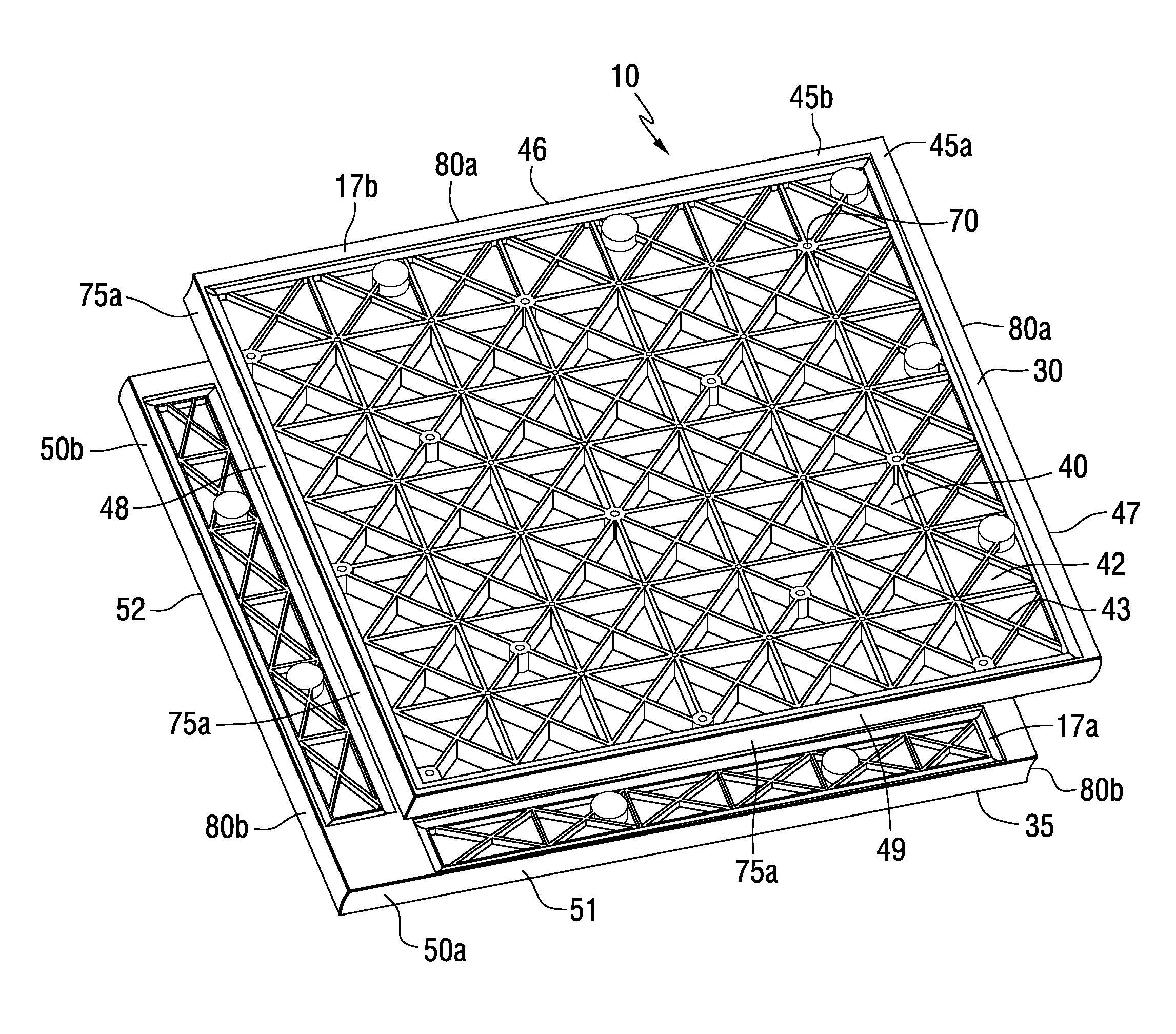
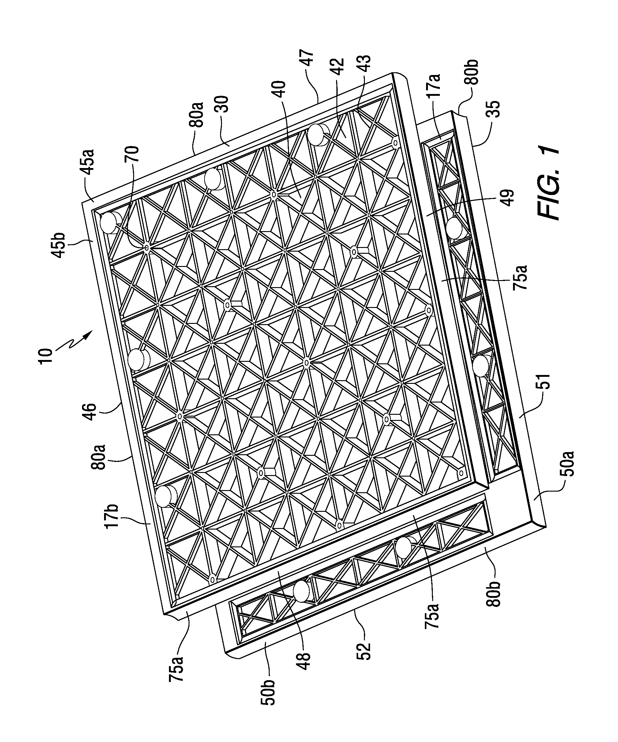
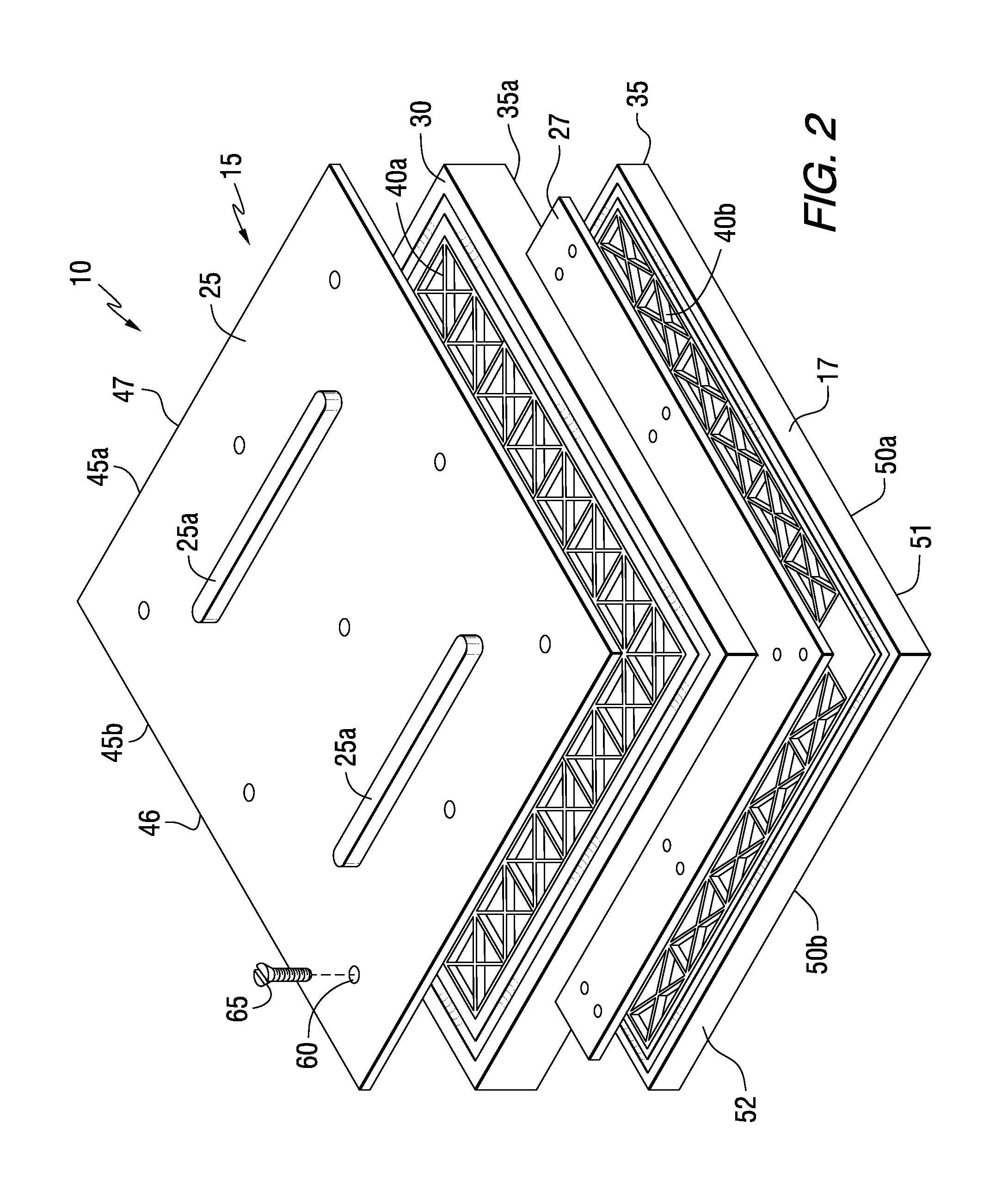
[0022]Referring to FIG. 1, an individual floor mat 10 of the invention is comprised of main body component 15 and flange components 17a, 17b. Main body 15 and flanges 17a, 17b and are constructed as one unit from a single piece of material. Main body 15 and flanges 17a, 17b have a generally upper planar surface 30 and main body 15 and flanges 17a, 17b have a generally planar lower surface 35 (not shown). Flanges 17a and 17b are positioned so that they are mutually offset relative to each other, thereby resulting in overhang or flange surfaces 45a, 45b on two adjacent peripheral edges 46 and 47 and flange surfaces 50a, 50b on two adjacent peripheral edges 51 and 52. Each of the modular floor mats 10, with the exception of the interchangeable aluminum cam 20 locks and top covers 25a and 25b, as hereinafter described in greater detail, is preferably formed as a one-piece unit from a single piece of material (FIG. 2). Modular floor mats 10 are provided for use as part of an interlocking...


PUM

PropertyMeasurementUnit
Areaaaaaaaaaaa

Abstract

A modular flooring system is disclosed which is designed to support heavy loads while providing stability and ground protection. The invention contemplates a modular mat having an integral main body with offset mounting and assembly flanges and a lattice interior. The mat is constructed from a unitary piece of high strength plastic. Each flange edge contains an outward radiused edge, while each non-flange edge contains an inward radiused edge. Each flange engages with a corresponding flange on an adjacent tile, allowing the outward radiused and inward radiused edges to properly mate. One or more metal cam locks located along the upper flange edges are secured into corresponding cam receptacles located along the lower flange edge. The mats may utilize optional top covers to prevent water and debris from entering the mats. The modular flooring system provides increased strength and stability and protection of the subsurface in heavy industrial applications.

Description

BACKGROUND OF THE INVENTION[0001]1. Field of the Invention[0002]The invention relates to a modular flooring and roadway system. More particularly, the invention relates to the use of modular floor mats which provide increased strength, stability and protection of the subsurface in heavy industrial applications.[0003]2. Description of the Prior Art[0004]Heavy duty modular flooring systems of various designs have been utilized for a significant period of time to provide a temporary and rigid surface in remote or inaccessible areas. More particularly, such systems are primarily utilized in settings where a firm and stable surface is temporarily needed, such as industrial or construction areas. With respect to industrial or construction areas, temporary flooring may be utilized to provide walkways, driveways, parking areas or other rigid surfaces for the transport of materials, vehicles, storage or mounting of equipment. The modular nature of such flooring is utilized to adapt the floor...

Claims


Application Information

Patent Timeline
IPC IPC(8): E04B5/00E04C2/52
CPCE01C2201/12E01C11/24E01C5/20E01C9/086E01C5/22
Inventor ROSAN, ARNON
Owner SIGNATURE SYST GRP LLC
Why Eureka
Try Eureka