Method and system for locating a laser vibrometer during non-contact scanning

a laser vibrometer and non-contact technology, applied in the field of non-contact scanning, can solve the problems of increasing the time and cost of performing the inspection

Active Publication Date: 2012-10-25
RTX CORP
View PDF14 Cites 15 Cited by
  • Summary
  • Abstract
  • Description
  • Claims
  • Application Information

AI Technical Summary

Problems solved by technology

Both methods for locating the vibrometer, however, require certain base assumptions (e.g., that the component is close to a nominal geometric location and shape, that the surface of the component can be represented by a two dimensional planar surface, that non-scalar image data can be used as a reference, etc.) and can increase time and costs associated with performing the inspection.

Method used


Image

  • Method and system for locating a laser vibrometer during non-contact scanning
  • Method and system for locating a laser vibrometer during non-contact scanning
  • Method and system for locating a laser vibrometer during non-contact scanning

Examples


Embodiment Construction

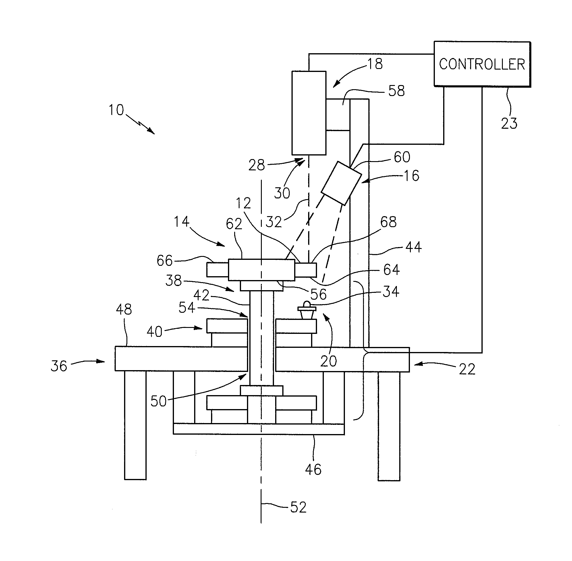
[0012]FIG. 1 illustrates a system 10 for inspecting a surface 12 of an object such as a rotor blade, generally referred to hereinafter as an “object 14”. The system includes an optical scanner 16, a laser vibrometer 18, an excitation system 20, a support stand 22 and a controller 23.

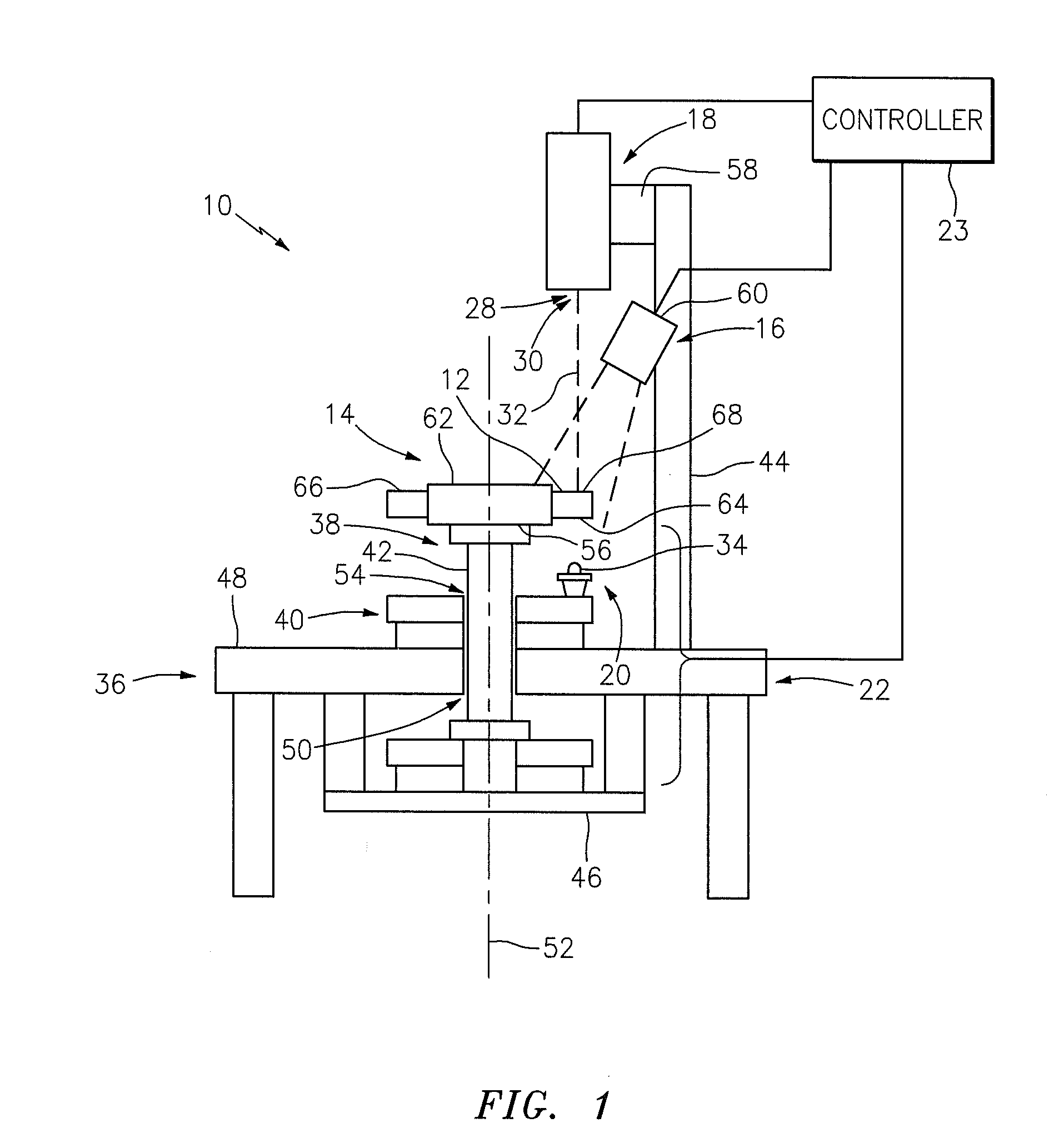
[0013]Referring to FIGS. 1 and 2, the optical scanner 16 is adapted to map at least a portion of the object surface 12. The term “map” is used herein to describe a process of applying a triangulated mesh of surface points to an object surface. In the embodiment shown in FIG. 2, the optical scanner 16 includes a fringe pattern projector 24 and one or more cameras 26. The projector 24 is adapted to project a point, line and / or pattern of light at one or more projection frequencies. Each camera 26 is adapted to capture an image within a light intensity band and a camera frequency band, which camera frequency band includes the projection frequencies. An example of such a projector and cameras is disclosed in...


PUM


Abstract

A method and system are provided for inspecting a surface of an object with an optical scanner and a laser vibrometer. The method includes the steps of: (a) mapping at least a portion of the object surface using the optical scanner; (b) projecting a beam of light from the laser vibrometer onto the object surface at a measurement point; (c) locating the measurement point relative to the object surface using the optical scanner; and (d) measuring a position of the object surface using the laser vibrometer to determine, for example, a deflection of the object surface.

Description

BACKGROUND OF THE INVENTION[0001]1. Technical Field[0002]This disclosure relates generally to non-contact scanning and, more particularly, to a method and system for spatially locating a laser vibrometer relative to an object.[0003]2. Background Information[0004]Machinery components or objects (e.g., gas turbine rotor blades) can be inspected using non-contact scanning. Vibrationally induced deflections and stresses of the component, for example, can be determined using data measured by a laser vibrometer. The deflections and stresses can subsequently be processed to predict or model how the component will respond to vibrations during operation of the component within the machinery (e.g., performance of the rotor blade within the gas turbine engine). In order to produce accurate predictions and models, however, the position of the vibrometer and, thus, the position of where the data is being measured on the component surface must be located relative to the component. The vibrometer ...

Claims


Application Information

Patent Timeline
Patent Type & Authority Applications(United States)
IPC IPC(8): G01H9/00
CPCG01B11/161G01B11/2545G01B11/25
Inventor BOYER, JESSE R.JOYNER, RANDALL W.
Owner RTX CORP
Why Eureka
Try Eureka