Outer plate carrier

a technology of outer plate and plate, applied in the direction of clutches, friction clutches, gearing details, etc., can solve the problems of high production cost of embodiment and high production cost of forging blank, and achieve the effect of simple and cost-effectiv

Active Publication Date: 2012-10-25
SCHAEFFLER TECH AG & CO KG
View PDF3 Cites 6 Cited by
  • Summary
  • Abstract
  • Description
  • Claims
  • Application Information

AI Technical Summary

Benefits of technology

[0008]In a first embodiment of the outer plate carrier, the geared sheath is welded to the hub shell and / or an axial stop of the bottom section of the carrier plate. Advantageously here a connection can be established in a simple and cost-effective manner between the geared sheath and the hub shell.
[0009]In an alternative embodiment of the outer plate carrier, the geared sheath comprises radially inwardly an inner gearing and is connected by way of caulking to the hub shell. Advantageously by this connection technology any change of the gearing of the geared sleeve can be avoided, caused by excessive introduction of heat. In one embodiment, the geared sheath comprises at its end facing the bottom section a chip chamber embodied as a circumferential recess. Advantageously, this chip chamber then can accept chips of the geared sheath developing during the caulking process.

Problems solved by technology

This embodiment is disadvantageous by its high production costs.
Particularly the production of the forging blank is expensive.

Method used


Image

  • Outer plate carrier
  • Outer plate carrier
  • Outer plate carrier

Examples


Embodiment Construction

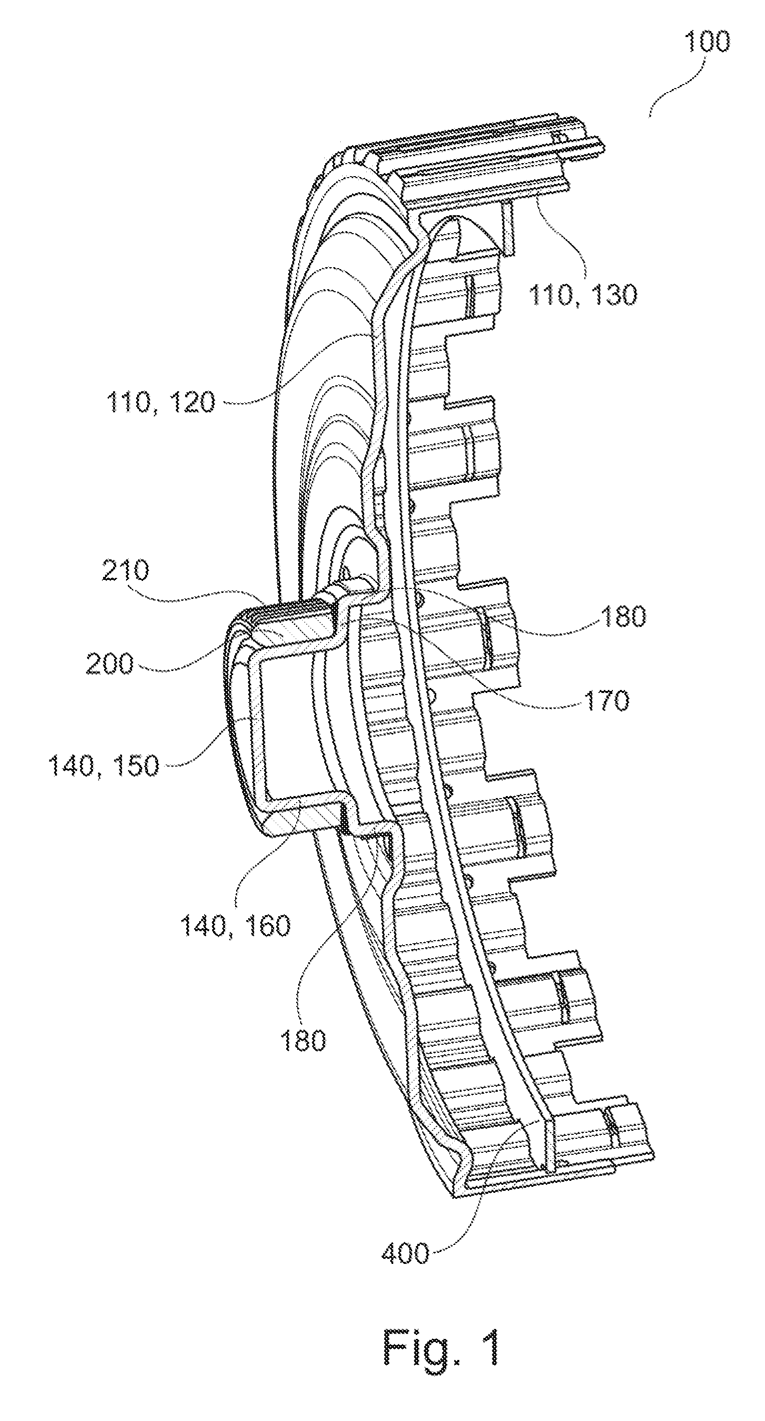
[0021]The outer plate carrier 100 may for example be used in a hydraulic clutch of a transmission of a motor vehicle embodied as a multi-disk clutch. The use of the outer plate carrier 100 in a hydraulic brake of a motor vehicle is also possible.

[0022]FIG. 1 is a schematic and partially opened, perspective illustration of outer plate carrier 100. The outer plate carrier 100 comprises a cup-shaped embodied carrier plate 110 with a circular-disk shaped bottom section 120 and a cylindrical-shell shaped cylinder section 130. The carrier plate 110 may be made from a material with low stability, for example steel of the quality DD12. The carrier plate 110 may be produced by way of deep-drawing, for example.

[0023]The cylinder section 130 of the carrier plate 110 comprises at its radially outer surface a plurality of inner suspended plates, which are embodied according to prior art and thus require no further explanation. The cylinder section 130 of the carrier plate 110 comprises a circumf...


PUM


Abstract

An outer plate carrier, including a cup-shaped embodied carrier plate (110) comprising a cylinder-shell shaped cylindrical section (130) and a circular-disk shaped bottom section (120). The bottom section (120) of the carrier plate (110) carries a cup-shaped hub section (140), arranged centrally. The cup-shaped hub section includes a cylindrical-shell shaped hub jacket (160) and a circular-disk shaped hub bottom (150). The hub bottom (150) has a smaller diameter than the bottom section (120) of the carrier plate (110). The hub bottom (150) is continuous and embodied in one piece with the carrier plate (110).

Description

CROSS-REFERENCE TO RELATED APPLICATIONS[0001]This application is filed under 35 U.S.C. §120 and §365(c) as a continuation of International Patent Application No. PCT / DE2010 / 001383 filed on Nov. 24, 2010, which application claims priority from German Patent Application No. 10 2009 058 622.9 filed Dec. 17, 2009, which applications are incorportated herein by reference in their entirety.FIELD OF THE INVENTION[0002]The present invention relates to an outer plate carrier for a clutch, for example, a clutch in a transmission.BACKGROUND OF THE INVENTION[0003]Outer plate carriers are essential components of hydraulic clutches and brakes, as for example used in motor vehicles. For example, an outer plate carrier represents a clutch inlet, transmitting a torque from an internal combustion engine to the plates of the outer plate carrier. Appropriate multi-disk clutches are known for example from DE 103 09 566 A1.[0004]Outer plate carriers of the prior art comprise a clutch basket and a connect...

Claims


Application Information

Patent Timeline
Patent Type & Authority Applications(United States)
IPC IPC(8): F16D13/58
CPCF16D13/683
Inventor NOEHL, OLIVERSCHLOSSER, MICHAELGUTT, THOMASFEURER, FRANK
Owner SCHAEFFLER TECH AG & CO KG
Why Eureka
Try Eureka