Universal Clamping Block

a technology of clamping block and universal clamping, which is applied in the field of clamping block, can solve the problems of inoperable devices, easy user error, and complex design of devices, and achieve the effects of reducing damage to structural elements, convenient manufacturing, and convenient us

Inactive Publication Date: 2012-10-25
SWANSON DAVID
View PDF18 Cites 0 Cited by
  • Summary
  • Abstract
  • Description
  • Claims
  • Application Information

AI Technical Summary

Benefits of technology

[0018]It is a further object of this invention to provide a mounting interface between a clamping component and material being joined in a joint, to reduce damage to the structural elements forming the resulting miter joint while also providing secure contact pressure.
[0019]It is another object of the invention to provide a device that is easily manufactured and easily used and therefor widely employable.
[0020]It is a further object of the invention to provide a device that is easily employed on any angle of a miter joint.
[0021]Another object of the invention is the provision of scaled markings along its length to aid in distance determination as needed.

Problems solved by technology

Due to the limited ability of a single laborer, miter joints must to be held in place by clamps, or similar apparatus to support the joint prior to glueing or nailing.
However, the device is overly complex in design and as such could be easily prone to user error.
Furthermore, the Hanson device involves many components that if misplaced, as can happen in a workshop, render the device inoperable.
In use however, means for engaging the device to the mitered elements involves inserting pins into the surface of the mitered elements leaving visible holes when removed.
Since it is often desired to maintain aesthetic appeal on visible surfaces especially on the construction of a picture frame or the like, the device and method of this patent are undesirable.
Many other prior art clamps especially those employing small clamping pads such as U.S. Pat. No. 2,941,557 to Baprawski are known to cause visible damage and are undesirable.
The above devices, as well as many other prior art miter clamps and similar clamping devices fall short in the areas mentioned.
Additionally, some are not only costly due to complexity and other issues, they are also bulky, and occupy an inordinate amount of space in the already cluttered construction or workshop environment.
Introduction of new and complex equipment that, although build upon technological progress and innovation, can cause unneeded frustration to the common laborer.

Method used


Image

  • Universal Clamping Block
  • Universal Clamping Block
  • Universal Clamping Block

Examples


Embodiment Construction

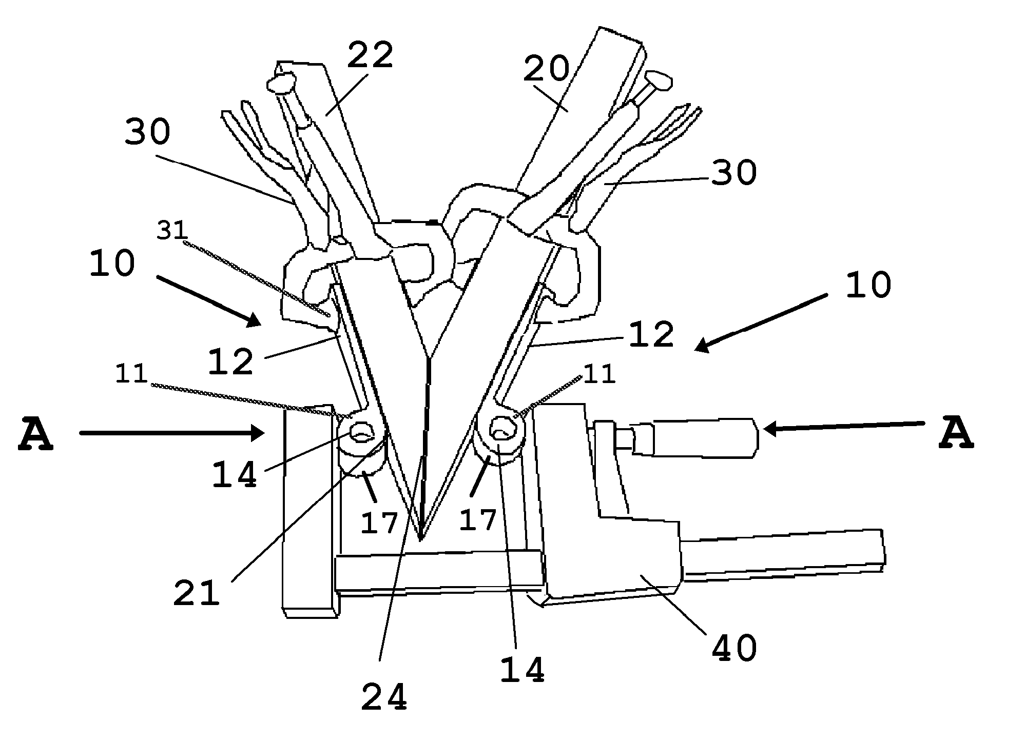
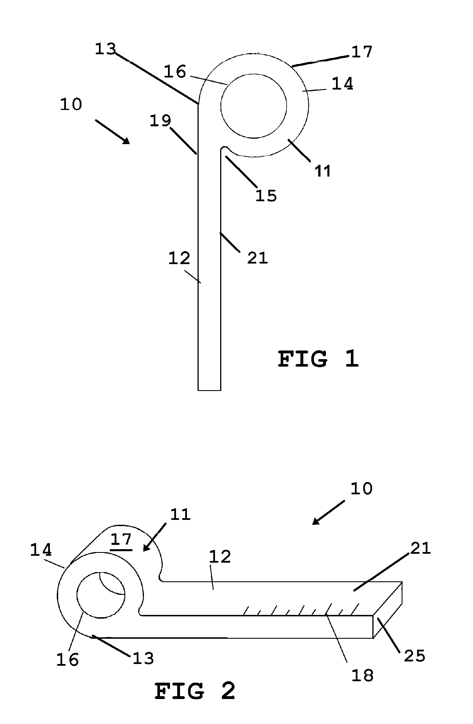
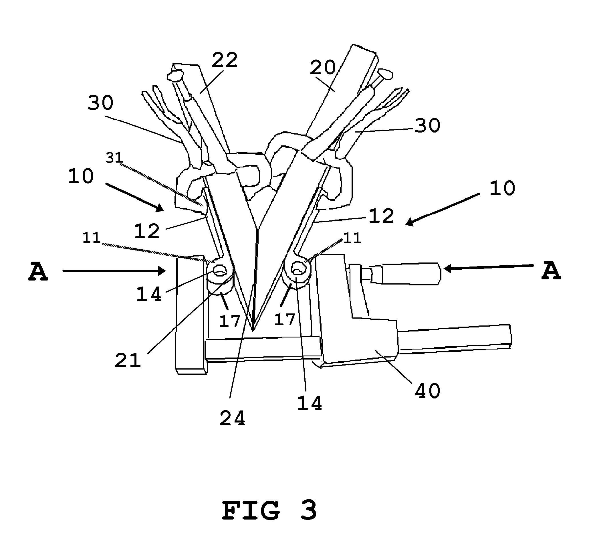
[0029]Now referring to drawings in FIGS. 1-6, wherein similar components are identified by like reference numerals, there is seen in FIG. 1 a side profile view of the device 10 in a preferred mode. As depicted, the device 10 consists of an elongated member 12 forming a body portion, having a substantially planar bottom or first planar surface 19 and parallel and substantially planar top or second planar surface 21. One or a plurality of projections 11 extend from the second planar surface 21 as shown in the drawing FIGS. 1,2, and 6.

[0030]The device 10 may be formed of hard plastic or ceramic materials, or most preferably of metal, by machining or molding or in an extrusion. A currently preferred mode of the device 10 is formed of an extruded material such as aluminum, hard plastic, or the like, which is then cut to size and its surfaces planed if necessary.

[0031]In the particularly preferred mode of the device 10 of FIGS. 1 and 2, in a unitary structure, a generally circular shaped ...


PUM


Abstract

An interface component is provided for use in combination with a clamp or compressive tool imparting a compressive force against respective planar contact surfaces of two components being joined at a miter joint. The interface features an elongated member having a projection projecting away from a top surface in a substantially circular path. The curved surface provides a means to redirect the compressive force communicated against said curved surface to the miter joint at a substantially normal angle.

Description

BACKGROUND OF THE INVENTION[0001]1. Field of the Invention[0002]The present invention relates to miter clamps and more particularly to a clamping block used with conventional clamping tools to assist in clamping miters and various angles in wood.[0003]2. Prior Art[0004]In construction of wooden frames such as picture frames, door frames, and the like, joining angled corners, know as miter joints, are engaged together often by adhesives, screws, or nails. Due to the limited ability of a single laborer, miter joints must to be held in place by clamps, or similar apparatus to support the joint prior to glueing or nailing. Prior art clamps have shown many attempts to accomplish this.[0005]U.S. Pat. No. 1,222,204 to Hanson teaches a clamping device used especially for the gluing of mitered corners of a frame. The clamp is adjustable along all edges of a typical frame construction and allows for adaptability for many types of miter joints. However, the device is overly complex in design a...

Claims


Application Information

Patent Timeline
Patent Type & Authority Applications(United States)
IPC IPC(8): B25B5/16
CPCB25B5/163B25B5/142
Inventor SWANSON, DAVID
Owner SWANSON DAVID
Why Eureka
Try Eureka