Apparatus and method for sealing pipes and underground structures

a technology for underground structures and apparatus, applied in mechanical apparatus, cable terminations, manufacturing tools, etc., can solve problems such as sewer system failure, system blockage, water infiltration, and sewer system failure, and achieve the effects of preventing the infiltration of water within the manhole, convenient installation, and economical manufactur

Active Publication Date: 2012-10-25
LMK TECH LLC
View PDF7 Cites 135 Cited by
  • Summary
  • Abstract
  • Description
  • Claims
  • Application Information

AI Technical Summary

Benefits of technology

[0012]It is another object, feature, and / or advantage of the present invention to provide a seal to both a portion of the interior of the buried pipe and the adjoining wall of the manhole.
[0013]It is another object, feature, and / or advantage of the present invention to prevent the infiltration of water within a manhole by sealing the areas between the bottom pan, the barrel, the cone, and the adjusting rings of a manhole by using a sealing member in conjunction with a manhole liner.
[0014]It is another object, feature, and / or advantage of the present invention to provide an apparatus and method for repairing a pipe, a manhole, or the junction between a pipe and a manhole which is economical to manufacture, easy to install, and durable in use.
[0015]It is another object, feature, and / or advantage of the present invention to provide an improved method and apparatus for repairing the junction of a pipe and a manhole that provides a compression seal to the majority of the area at the junction.
[0016]It is another object, feature, and / or advantage of the present invention to provide an end seal for repairing the end of a pipe that provides a compression seal to the majority of the area at the pipe end.
[0017]It is another object, feature, and / or advantage of the present invention to provide a sealing member for use in conjunction with a pipe or manhole liner to repair or seal an area prone to experiencing water infiltration where the sealing member may be a compressible material, an absorbent material, or a hydrophilic or hydrophobic rubber or grout.

Problems solved by technology

As the infrastructure of major cities and towns in the developed world age, the sewer systems weaken.
Pipe degradation, system blockage, water infiltration, and sewer leakage are major problems that aging sewer systems experience.
As these problems persist, the sewer system may eventually experience total failure and entire sections of the sewer system may collapse.
As a result, sinkholes may form and sewers may back up into homes and places of business.
Even in sewer systems where the main pipes have been rehabilitated with a cured-in-place pipe or other pipe liners, problems still arise.
Some of those problems are caused by shrinkage of the pipe liner and unsealed areas at the pipe ends, the pipe junctions, or the manholes and other adjoining structures.
Shrinkage of a pipe liner after installation presents a problem for the longevity and effectiveness of a sewer system or other pipeline.
Most materials experience some shrinkage after installation within an existing pipe.
There are several problems with this method.
First, the step of spraying the material onto the pipe may be time consuming and the sprayed-on material may fall off of the pipe or sag to the bottom of the pipe due to gravity.
Second, there is no way of determining whether the expandable material has expanded sufficiently into the annular space during the curing process, as the liner obstructs the view of the annular space.
Third, the step of spraying the material onto the pipe is imprecise as there may be areas of the main pipe that receive too much or too little expandable material resulting in an uneven wall thickness.
Additionally, the sprayed-on material may be moved by ground water leaking through cracks into the pipe.
In sewer systems where the main pipes have been rehabilitated with a cured-in-place pipe, unsealed connections at service and manhole junctions create problems.
Once service is reinstated to the service pipes by the use of the cutting tool, the service pipes may still include leaks, cracks or other structural defects that allow infiltration or exfiltration of fluids or sediment at or around the junction of the main and service pipe.
Once the main pipe and the junctions of the main and service pipes have been rehabilitated and sealed, the manhole and the junction of the main pipe and the manhole (or “main pipe / manhole junction”) remain at risk for allowing unwanted infiltration or exfiltration of fluids and sediment.
Additionally, in a conventional manhole, the areas between the bottom pan, the barrel, the cone, and the adjusting rings are prone to experiencing water infiltration and exfiltration even when a manhole liner has been installed.
This method is time consuming, requires the use of a tubular member to act as a mold for the area around the junction, does not address the problem of annular space around the pipe liner, and does not create a fluid-tight seal around a substantial area of the main pipe / manhole junction.
With such a method, it is unclear how to fully seal the junction of a manhole and a main pipe, as the shrinkage of the cured-in-place pipe will still allow ground water to infiltrate the annular space.
Additionally, there are deficiencies to other known methods of sealing pipe junctions when applied to the junction of a manhole and a pipe.
For example, the use of a band or o-ring as taught by U.S. Pat. No. 6,994,118 and U.S. Pat. Pub. 2009 / 0056823 would result in imprecise placement within the host pipe, as the flexible o-ring or band may shift within the pipe or fall during placement of a pipe liner.
The use of such a rope to seal the junction of a manhole and a pipe would result in imprecise placement within the host pipe, as there are no structural elements allowing the flexible rope to remain in place.
Furthermore, the use of such a rope would not provide a complete seal, because the rope would be unconnected at its ends, allowing water or other fluid to track along the edge of the rope and leak at the point where the ends abut.

Method used


Image

  • Apparatus and method for sealing pipes and underground structures
  • Apparatus and method for sealing pipes and underground structures
  • Apparatus and method for sealing pipes and underground structures

Examples


Embodiment Construction

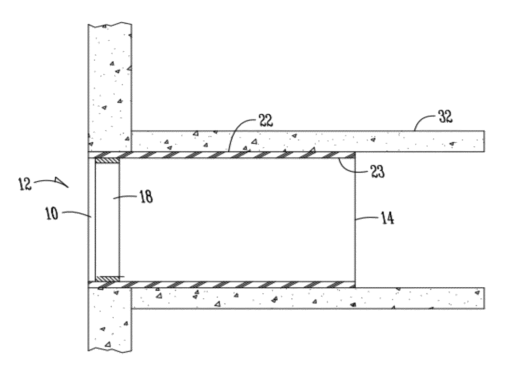
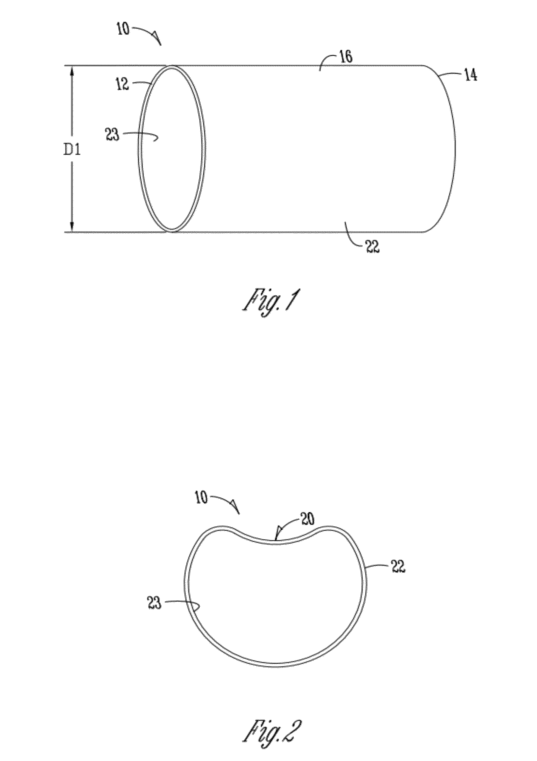
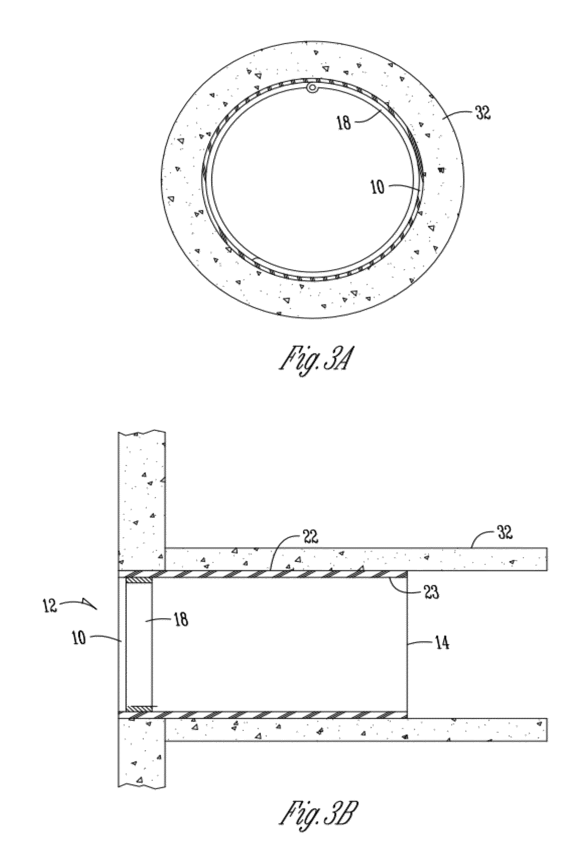
[0035]The present invention relates to an apparatus and method for repairing or sealing a manhole or other underground structure, the junction between a manhole or other underground structure and a pipe in fluid communication therewith, or the end of a buried pipe, such as underground sewer pipe and the like. The end of a pipe is sealed with the use of a pipe liner and a sealing member. Alternatively, a manhole or other underground structure is sealed by the use of one or more sealing members and a manhole liner.

[0036]The following definitions of terms are employed throughout the specification and claims:

[0037]A “pipe liner” is defined as a material that is used to provide a lining to a pipe. Pipe liners include but are not limited to cured-in-place pipe liners, folded liners, or spray-on liners.

[0038]A “cured-in-place pipe liner” is a fabric capable of holding a resinous material.

[0039]A “folded liner” is a material constructed of a thermoplastic, such as High Pressure Polyethylene...


PUM

PropertyMeasurementUnit
lengthaaaaaaaaaa
lengthaaaaaaaaaa
diameteraaaaaaaaaa

Abstract

An apparatus and method for sealing pipes or underground structures is provided. In one embodiment, the end of a pipe is sealed by the use of a pipe liner and a sealing member. The sealing member may be a hydrophilic material, a hydrophobic material, a compressible material, or a paste. The sealing member is held in place by a mechanical fastener and a liner is installed adjacent the sealing member and against the wall of the pipe or other structure to be sealed. In another embodiment, a manhole is sealed by the use of a sealing member, a mechanical fastener, and a manhole liner.

Description

CROSS-REFERENCE TO RELATED APPLICATIONS[0001]This application is a continuation-in-part of pending U.S. patent application No. 12 / 962,276, filed on Dec. 7, 2010, which is herein incorporated by reference in its entirety.FIELD OF THE INVENTION[0002]The invention relates generally to an apparatus and method for repairing or sealing a manhole or other underground structure, the junction between the manhole or other underground structure and a pipe in fluid communication therewith, or the end of a buried pipe, such as underground sewer pipe and the like. More particularly, but not exclusively, the invention relates to a kit, apparatus, and method to seal a pipe, an underground structure such as a manhole, or a junction using liners in conjunction with a sealing member using a mechanical fastener to hold the sealing member in place during liner installation.BACKGROUND OF THE INVENTION[0003]As the infrastructure of major cities and towns in the developed world age, the sewer systems weake...

Claims


Application Information

Patent Timeline
Patent Type & Authority Applications(United States)
IPC IPC(8): F16J15/02F16L19/00F16J15/10B23P11/00
CPCF16L55/179F16L55/163Y10T29/49826E02D29/128F16L55/18
Inventor KIEST, JR., LARRY W.
Owner LMK TECH LLC
Why Eureka
Try Eureka