Multibeam radar apparatus for vehicle, multibeam radar method, and multibeam radar program

a multi-beam radar and vehicle technology, applied in the direction of multi-channel direction-finding systems using radio waves, antennas, instruments, etc., can solve the problems of small beam width and large number of beams, limited resolution or angle measurement accuracy of multiple targets at the same measurement point, and difficulty in realizing a plurality of detection functions with various fovs in a single radar apparatus, and achieve high accuracy

Inactive Publication Date: 2012-10-25
NAT UNIV CORP SHIZUOKA UNIV +1
View PDF11 Cites 61 Cited by
  • Summary
  • Abstract
  • Description
  • Claims
  • Application Information

AI Technical Summary

Benefits of technology

[0024]According to the invention, it is possible to provide an on-board multibeam radar apparatus, a multibeam radar...

Problems solved by technology

In practice, the small beam width and the large number of beams are limited from the viewpoint of structure and cost, and the resolution or the angle measurement accuracy of multiple targets at the sa...

Method used


Image

  • Multibeam radar apparatus for vehicle, multibeam radar method, and multibeam radar program
  • Multibeam radar apparatus for vehicle, multibeam radar method, and multibeam radar program
  • Multibeam radar apparatus for vehicle, multibeam radar method, and multibeam radar program

Examples


first embodiment

Conclusion of First Embodiment

[0204]Although it has been stated in the first embodiment that the FMCW system is exemplified as the radar system, the invention is not limited to the radar system and the constitution according to the first embodiment may be applied to another radar system.

[0205]Although it has been stated in the first embodiment that the MUSIC method is exemplified as the high-resolution algorithm, the constitution according to the first embodiment may be applied to other techniques such as a linear prediction method or a beam forming method. For example, it is possible to calculate an azimuth angle (angle) using virtual array data and virtual array steering vectors.

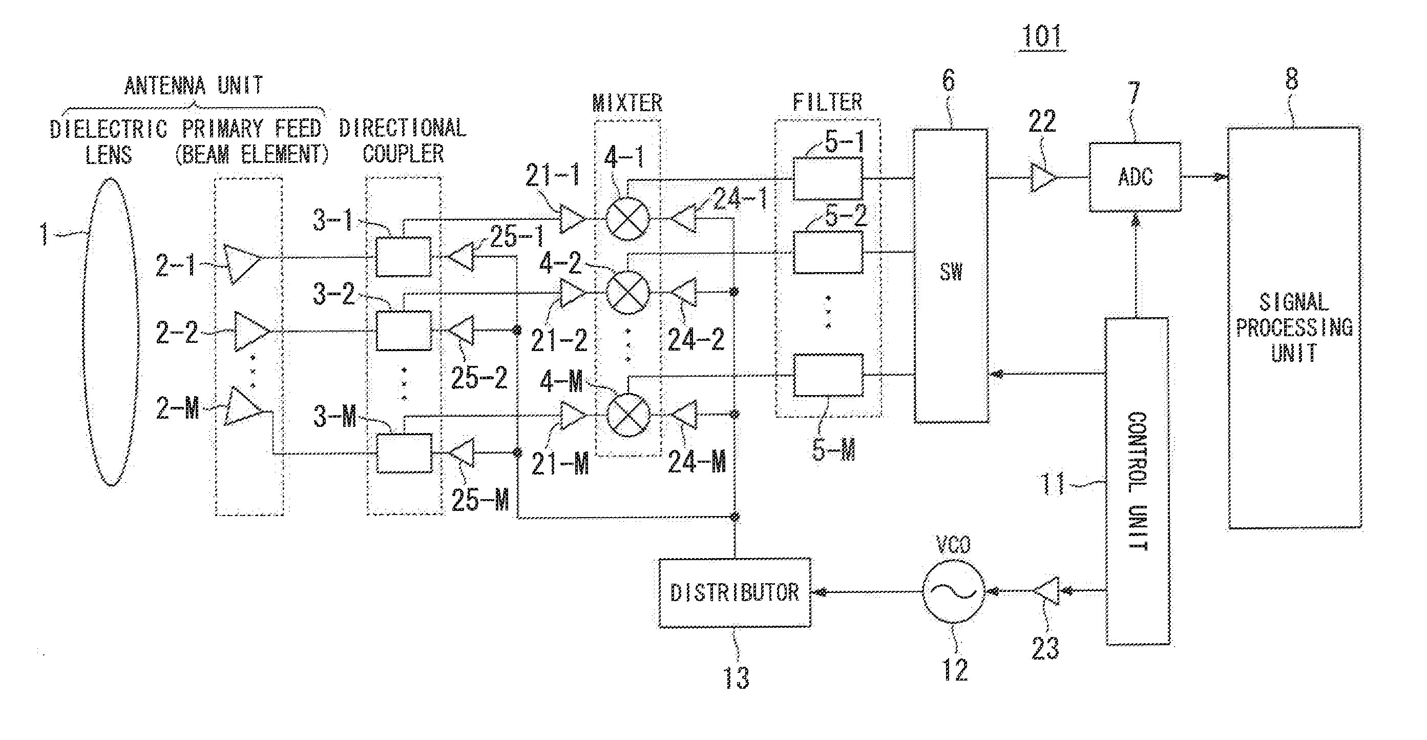
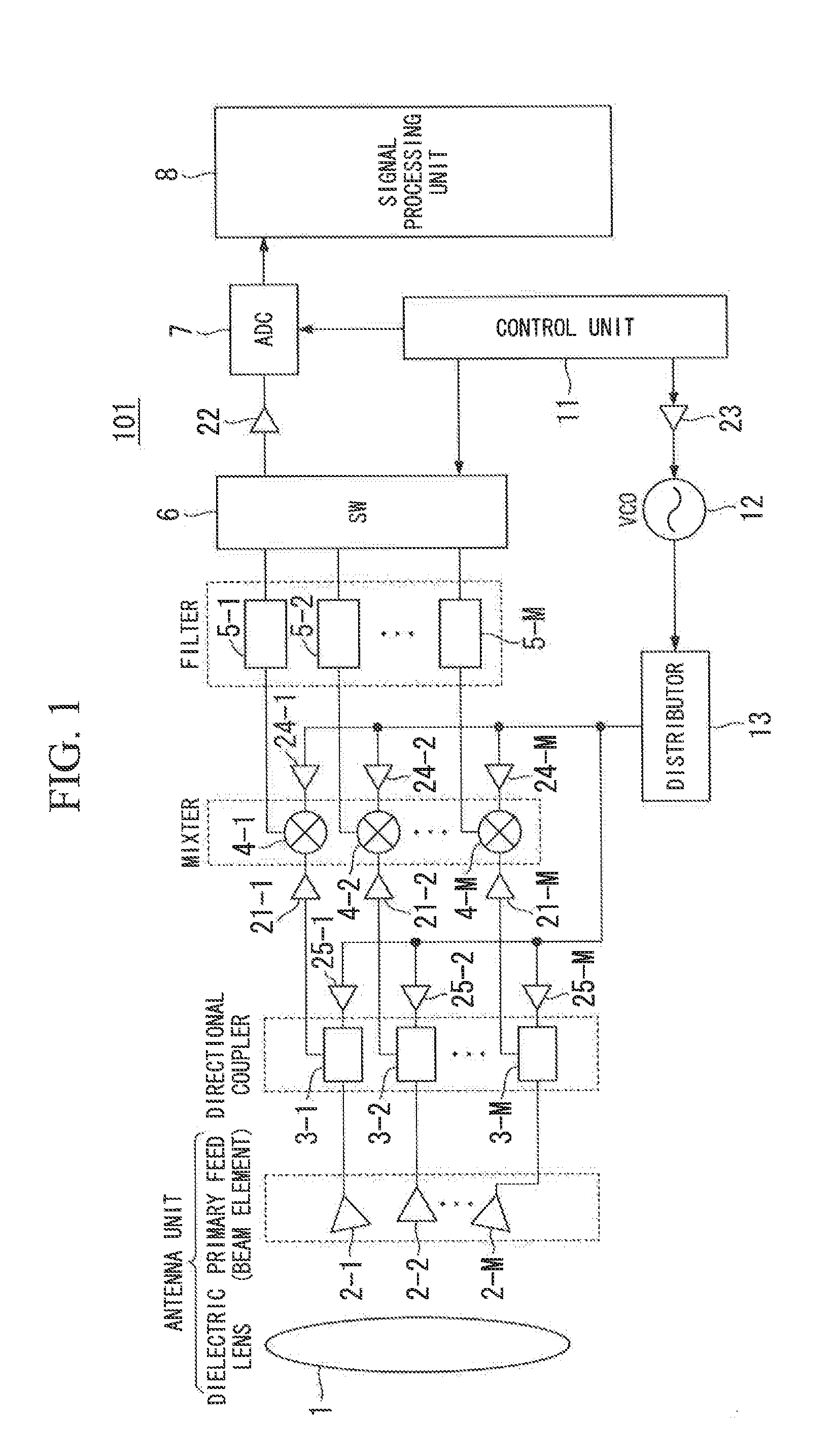
[0206]As described above, the multibeam radar apparatus 101 according to the first embodiment include Apparatus Constitution 1 to Apparatus Constitution 4 described below.

[0207]As Apparatus Constitution 1, the multibeam radar apparatus 101 according to the first embodiment performs the Fourier transformati...

second embodiment

Conclusion of Second Embodiment

[0251]As described above, the multibeam radar apparatus 101 according to the second embodiment includes Apparatus Constitution 5 described below.

[0252]As Apparatus Constitution 5, the multibeam radar apparatus 101 according to the second embodiment applies the unitary transformation to the correlation matrix Rxx based on the virtual array data Y(n) and the virtual array steering vector a(n, θ) using the conjugate centrosymmetry of the virtual array and then performs the direction estimation, when performing the direction estimation using the MUSIC method as a high-resolution algorithm through the use of Apparatus Constitution 1 to Apparatus Constitution 4.

[0253]Since the multibeam radar apparatus 101 according to the second embodiment includes Apparatus Constitution 5 and thus can perform the eigenvalue decomposing process using the real correlation matrix, it is possible to achieve functional advantages of reducing the computational load and more perf...

third embodiment

Conclusion of Third Embodiment

[0332]Although it has been stated in the third embodiment that the FMCW system is exemplified as the radar system, the invention is not limited to the radar system and the constitution according to the third embodiment may be applied to another radar system.

[0333]Although it has been stated in the third embodiment that the MUSIC method is exemplified as the high-resolution algorithm, the constitution according to the third embodiment may be applied to other techniques such as a linear prediction method or a beam forming method. For example, it is possible to calculate an azimuth angle (angle) using virtual array data and virtual array steering vectors.

[0334]As described above, the multibeam radar apparatus 102 according to the third embodiment includes Apparatus Constitution 6 to Apparatus Constitution 8 described below.

[0335]As Apparatus Constitution 6, the multibeam radar apparatus 102 according to the third embodiment controls the transmission and re...


PUM


Abstract

An on-board multibeam radar apparatus includes a plurality of beam elements that constitute an antenna transmitting a transmission wave and receiving an incoming wave being reflected and arriving from a target in response to the transmission wave, a control unit configured to select a beam element used for transmission and reception out of the plurality of beam elements so as to change a field of view, and a processing unit configured to apply a Fourier transformation to beam element data which are data of a received wave received through the beam element used for transmission and reception selected by the control unit based on the number of elements and the element interval of a desired virtual array antenna so as to create virtual array data, and to perform a predetermined process based on the created virtual array data.

Description

CROSS-REFERENCE TO RELATED APPLICATIONS[0001]This application is a Non-provisional patent application of U.S. Provisional Patent Application No. 61 / 441,828, filed Feb. 11, 2011, and claims priority on Japanese Patent Application No. 2011-183054, filed Aug. 24, 2011, the contents of which are entirely incorporated herein by reference.BACKGROUND OF THE INVENTION[0002]1. Field of the Invention[0003]The present invention relates to an on-board multibeam radar apparatus, a multibeam radar method, and a multibeam radar program, which can detect a target using a reflected wave from the target in response to a transmitted wave.[0004]2. Background Art[0005]In recent years, on-board detection apparatuses measuring the distance, the relative velocity, and the azimuth between a vehicle and another vehicle (which is also referred to as a reflecting object, an object, or a target) using a millimeter wave radar or the like have been practically used. As on-board radars, an FMCW (Frequency Modulate...

Claims


Application Information

Patent Timeline
IPC IPC(8): G01S13/00G01S13/931
CPCG01S3/74G01S13/931G01S13/48G01S13/42
Inventor KUWAHARA, YOSHIHIKOKANAMOTO, JUNJIKAMO, HIROYUKI
Owner NAT UNIV CORP SHIZUOKA UNIV
Why Eureka
Try Eureka