Bone alignment implant and method of use

a bone alignment and implant technology, applied in bone drill guides, medical science, surgery, etc., can solve the problems of deformation of the limb and biomechanical abnormalities, disruption of healthy limb growth, and risk to the neurovascular structure, so as to reduce the chance of damage to the physis and constrain the volume of bone growth

Inactive Publication Date: 2012-10-25
AMEI TECH
View PDF7 Cites 17 Cited by
  • Summary
  • Abstract
  • Description
  • Claims
  • Application Information

AI Technical Summary

Benefits of technology

[0018]The distal end of the guide wire is used to locate the physis. Once its tip is placed in the physis, it is driven partly into the physis to function as a temporary guide for the link. The delivery of the implant over the guide wire assures that the link is properly placed with the bone fasteners on opposite sides of the physis. This will minimize the chance of damaging the physis throughout bone realignment. The link is then placed over the guide wire and oriented such that openings through the link for the bone fasteners are on either side of the physis. For pure angular correction, these openings would be collinear with the long axis of the bone; for rotational correction, they would be oblique to its axis.
[0019]The bone fasteners are then placed through the openings in the link and into the bone, connecting the sections of bone on opposite sides of the physis with the implant. Alternatively, guide pins can be used to help align cannulated fasteners.
[0020]The implant is designed such that it partially constrains the volume of the bone growth on the side of the physis that it is placed. The implant guides the growth of new bone at the physis such that the growth direction and resulting alignment is controlled. The implant limits the semi-longitudinal translation of the bone fasteners yet allows for the bone fasteners to freely rotate with the bone segments as the angular or torsional deformity is straightened.
[0021]In some embodiments of this invention, both the link and the fasteners are rigid, but the connection between them allows for relative movement of the fasteners. In other embodiments the link is flexible allowing the fasteners to move with the bone sections. In other embodiments, the fasteners have flexible shafts allowing only the bone engager of the fasteners to move with the bone sections. In still other embodiments, both the link and the shafts of the fasteners are flexible, allowing movement of the bone sections.

Problems solved by technology

As a result of congenital deformation, traumatic injury or other causes, long bones such as the femur, tibia and humerus may grow out of alignment, causing deformity of the limb and biomechanical abnormalities.
Because osteotomy methods require a relatively large incision to create bone cuts, they are relatively invasive; they disrupt the adjacent musculature and may pose a risk to the neurovascular structures.
An additional disadvantage of these procedures is the potential risk of damage to the growth plate, resulting in the disruption of healthy limb growth.
Since the bone is free to grow on the concave side of the deformity, the bone tends to grow on the unstapled side, causing the bone to realign over time.
They are not designed to allow flexibility or rotation of the stapled legs with the bone sections as the bone is realigned.
Due to the constraints of these staple implants, the planning associated with the placement of the implants is overly complicated.
Depending on the strength of the implant, these loads could eventually cause the implants to fracture under the force of bone realignment.
This can make them difficult or impossible to remove.
These same forces can also cause the implants to deform, weakening the bone-to-implant interface.
This weakening may result in migration of the implant out of the bone, risking damage to the adjacent soft tissues and failure of the procedure.
The use of braces in such patients may be emotionally difficult, negatively impacting self-image and self-esteem.
Surgical treatment options entail risks of spinal cord or nerve damage, failure of the bones to fuse, and spine infection.
Moreover, successful bone fusion results in impaired spinal motion which could limit or prevent certain physical activities.
Impaired mobility appears to have a particularly negative impact in children and young adults as it generally prevents their participation in sports and social activities.
In addition, the impaired mobility concomitant with spinal fusion increases the likelihood of back pain as the patient ages.
Depending on the strength of the implant, these loads could eventually cause the implants to fracture.
This can make them difficult or impossible to remove.
These same forces can also cause the implants to deform, weakening the vertebra-to-implant interface.
This weakening may result in migration of the implant out of the vertebra, risking damage to the adjacent soft tissues.
Such risk is particularly high in the spinal column where damage to adjacent tissues could result in permanent disability or worse, or depending on the location of the staple and its migration.
Such staples, however, are not useful in correction of spinal rotation.
That is, pronged staples are limited to use in cases of two-dimensional curvature; anterior-posterior, medial-lateral, and cranial-caudal.

Method used


Image

  • Bone alignment implant and method of use
  • Bone alignment implant and method of use
  • Bone alignment implant and method of use

Examples


Embodiment Construction

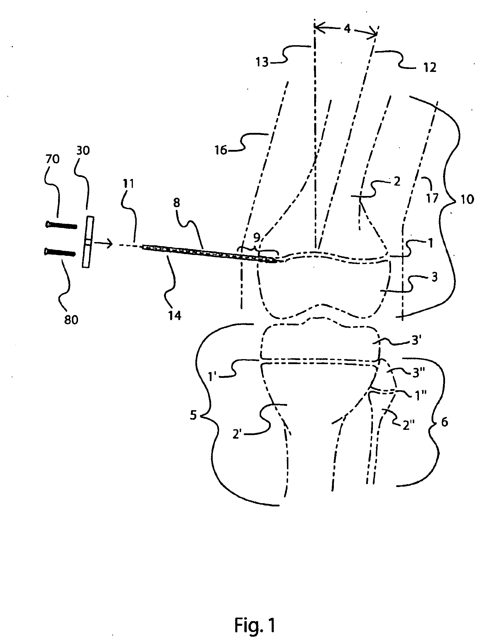
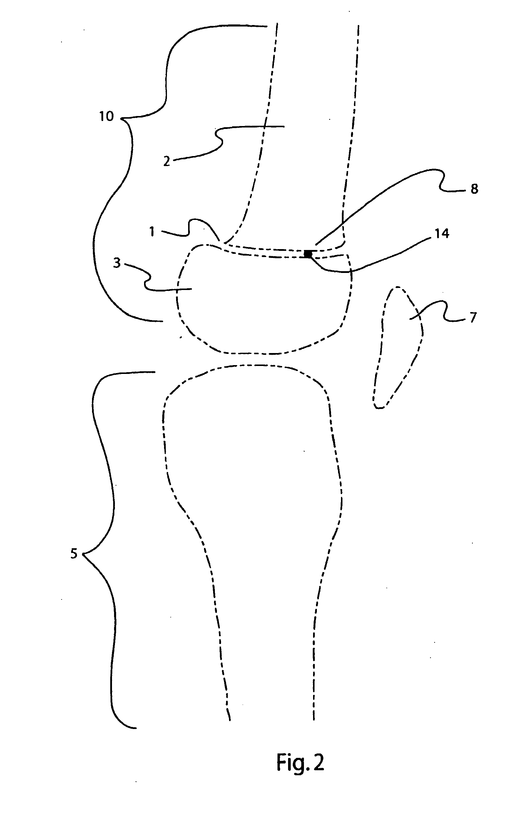
[0081]Referring to FIG. 1, a schematic anterior view of the human knee joint is depicted in which a distal femur 10 is proximal to a proximal tibia 5 and a proximal fibula 6. A distal femoral physis 1, or growth plate, separates a distal metaphyseal section 3 from a proximal diaphyseal section 2 of the distal femur 10 Likewise a proximal tibial physis 1′ separates a proximal metaphyseal section 3′ from a diaphyseal section 2′ of the proximal tibia 5 and a proximal fibula physis 1″ separates a proximal metaphyseal section 3″ of a proximal fibula 6 from a diaphyseal section 2″ of the proximal fibula 6. Although the invention described herein is adaptable to nearly all of the long bones in the body, only the example of correcting one type of an angular deformity in the distal femur will be described in detail. The principles described herein can be adapted to other deformities and other bones such as the tibia, fibula, humerus, radius and ulna.

[0082]By example, an angular deformity 4 i...


PUM


Abstract

A bone alignment implant includes a first bone fastener with a first bone engager that is adapted for fixation into the metaphyseal bone and a second bone fastener with a second bone engager that is adapted for fixation into the diaphyseal bone. A link connecting the two fasteners spans across the physis. Alternatively, the bone alignment implant is adapted for fixation into the diaphyseal sections of two adjoining vertebral bodies. These implants act as a flexible tethers between the metaphyseal and the diaphyseal sections of bone during bone growth. These implants are designed to adjust and deform during the bone realignment process. When placed on the convex side of the deformity, the implant allows the bone on the concave side of the deformity to grow. During the growth process the bone is then realigned. A similar procedure is used to correct torsional deformities.

Description

CROSS-REFERENCE TO RELATED APPLICATION[0001]The present application is a divisional application of U.S. patent application Ser. No. 11 / 244,879 entitled “BONE ALIGNMENT IMPLANT AND METHOD OF USE” filed Oct. 6, 2005, the entirety of which is hereby incorporated by reference.FIELD OF THE INVENTION[0002]The present invention relates to the design and method of use for an implant to help realign spinal angular and rotational deformities. More particularly, the present invention relates to a method for correcting spinal deformities in patients with active growth plates.BACKGROUND OF THE INVENTION[0003]As a result of congenital deformation, traumatic injury or other causes, long bones such as the femur, tibia and humerus may grow out of alignment, causing deformity of the limb and biomechanical abnormalities. While some deformities are asymptomatic or may resolve spontaneously, it is often necessary to intervene surgically to realign these limbs. For the patients requiring surgical interve...

Claims


Application Information

Patent Timeline
Patent Type & Authority Applications(United States)
IPC IPC(8): A61B17/88A61B17/70
CPCA61B17/0401A61B17/1757A61B17/1764A61B17/68A61B17/7022A61B17/7059A61B17/8085A61B17/848A61B17/86A61B17/8625A61B2017/0419A61B2017/044A61B2017/0647A61B2017/0648A61B17/0642A61B17/8061A61B17/16A61B17/17A61B17/80
Inventor STEVENS, PETER M.REINECKE, STEVEN M.VASTA, PAUL J.THOMAS, MICHAEL GREGORY
Owner AMEI TECH
Why Eureka
Try Eureka