Controlled flow air precleaner

a technology of controlled flow and precleaner, which is applied in the direction of machine/engine, combustion-air/fuel-air treatment, and separation processes to achieve the effect of reducing pressure losses

Inactive Publication Date: 2012-11-01
DEERE & CO
View PDF3 Cites 3 Cited by
  • Summary
  • Abstract
  • Description
  • Claims
  • Application Information

AI Technical Summary

Benefits of technology

[0010]The invention provides an air precleaner for removing entrained contaminants from intake air prior to ...

Problems solved by technology

The precleaner is designed to control the air flow to significantly reduce static and dynamic pressure losses that would otherwi...

Method used


Image

  • Controlled flow air precleaner
  • Controlled flow air precleaner
  • Controlled flow air precleaner

Examples


Embodiment Construction

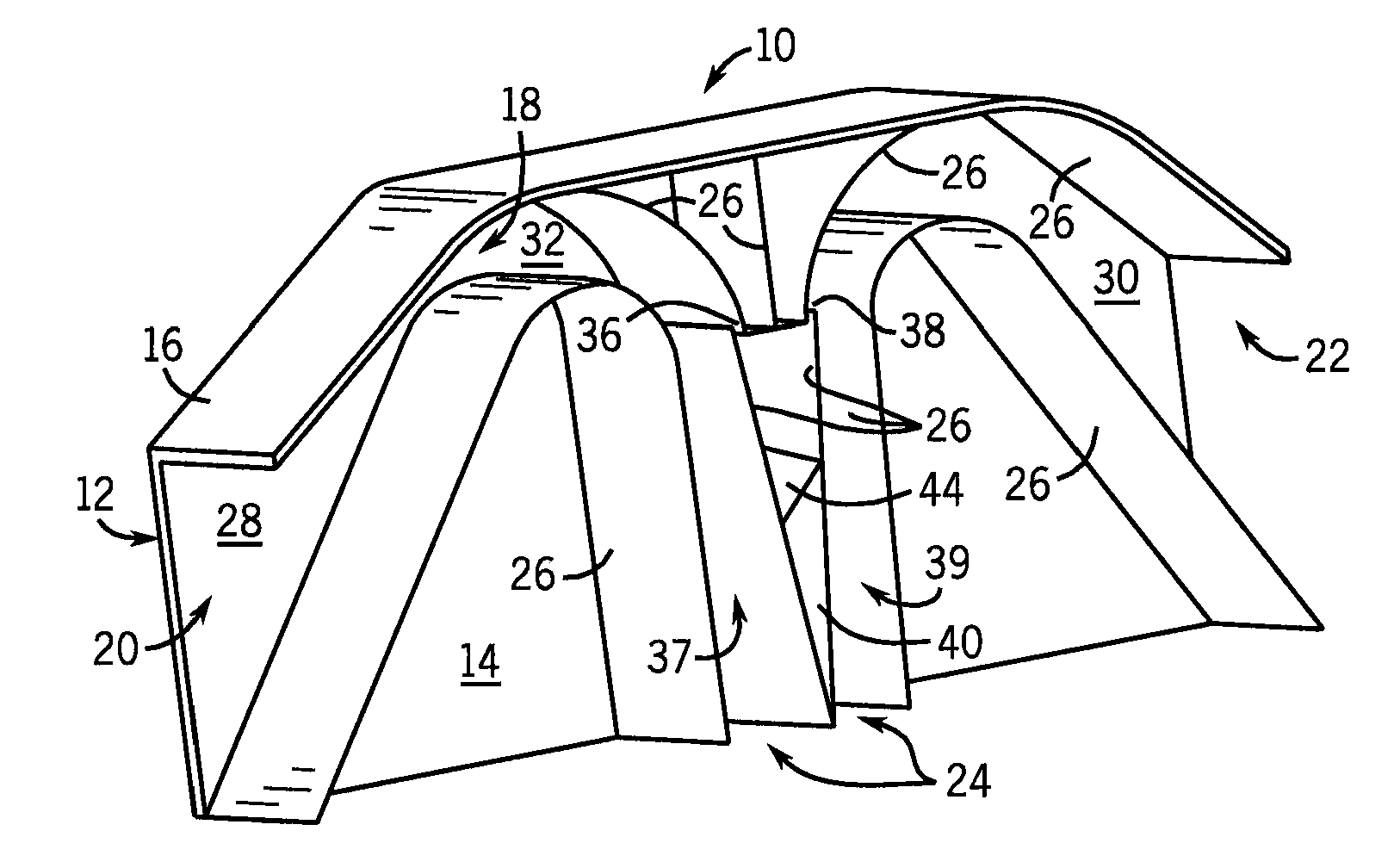
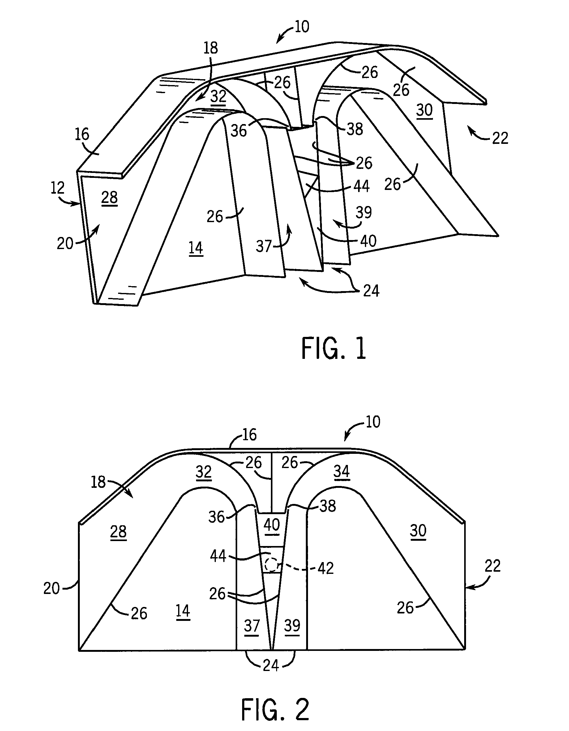
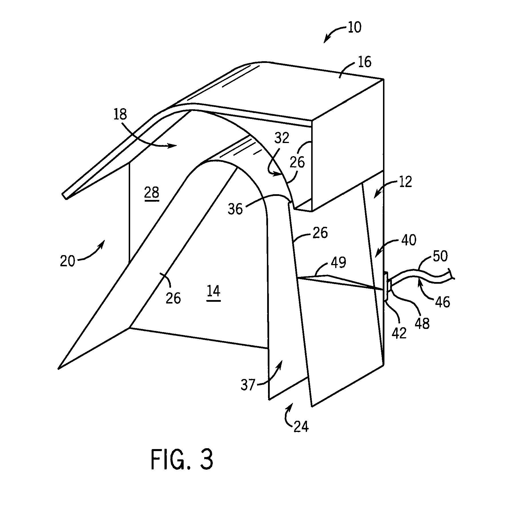
[0022]Referring to FIGS. 1-5, a precleaner 10 of the present invention has a housing 12 with opposite planar sides 14 and lateral side walls 16 defining an air chamber 18. The air chamber 18 has two opposite inlet openings 20 and 22 at the ends and a central outlet opening 24. The housing 12 contains a plurality of smooth vanes 26 extending perpendicularly between the sides 14. To promote easy formation and assembly of the precleaner 10, it is contemplated that at least one of the sides 14 and the vanes 26 may be integrally molded from a suitable polymer. Wire mesh screens may be disposed over the inlet openings 20 and 22 to prevent large debris from entering the precleaner 10.

[0023]The vanes 26 are arranged and shaped to have curved and straight portions as needed to define two air flow pathways 28 and 30 leading from each respective inlet openings 20 and 22 to the outlet opening 24. The pathways 28 and 30 are widest, that is have the greatest cross-sectional area, at the inlet ope...


PUM

PropertyMeasurementUnit
Angleaaaaaaaaaa
Gravityaaaaaaaaaa
Velocityaaaaaaaaaa

Abstract

An air precleaner includes a housing defining an air chamber with a downwardly opening outlet and a pair of side inlets. A plurality of vanes in the air chamber define two pathways for intake air to flow from the inlet openings around bends of more than 90 degrees to the outlet opening. The pathways initially narrow to increase the velocity of air in the bends. An ejection compartment between the pathways includes two ejection openings at the ends of the bends for receiving contaminants transferred to an outer layer of the air by centrifugal force. The collected contaminants exit the housing through an evacuation opening. Downstream of the ejection openings, the pathways gradually widen to decrease the velocity of the precleaned air prior to reaching the outlet opening. The precleaner may be applied to an engine intake air cleaner or to the intake air of a cooling package.

Description

CROSS-REFERENCE TO RELATED APPLICATIONS[0001]This application claims the benefit of U.S. Provisional Patent Application Ser. No. 60 / 980,935, filed on Oct. 18, 2007, which is hereby incorporated by reference in its entirety.STATEMENT OF FEDERALLY SPONSORED RESEARCH / DEVELOPMENT[0002]Not applicable.BACKGROUND OF THE INVENTION[0003]This invention relates to a precleaner such as used for the air intake system of a heavy duty vehicle.[0004]Air often includes particulate matter such as dirt, dust, sand, snow and the like. While most engines include air filters designed to remove such contaminants from the air that feeds the engine, these filters may quickly become saturated and need replacement. To extend the life of air filters, extend the engine's life, and improve fuel economy, air precleaners have been added to many engines. Air precleaners commonly remove entrained contaminants or particulates from the intake air before the air enters an air filter of an internal combustion engine. Ad...

Claims


Application Information

Patent Timeline
IPC IPC(8): B01D45/08
CPCB01D45/12F02M35/024F02M35/022
Inventor JAMES, MICHAEL F.
Owner DEERE & CO
Why Eureka
Try Eureka