Control device with thumb trigger

a control device and thumb trigger technology, applied in the direction of cycle control systems, cycle equipment, instruments, etc., can solve the problems of manual control that has to be actuated, control of a system that requires a rapid reaction, and the difficulty of vigorous grasping of the handle of the machine, so as to achieve optimal grip

Inactive Publication Date: 2012-11-01
VELLUTINI FREDERIC
View PDF0 Cites 3 Cited by
  • Summary
  • Abstract
  • Description
  • Claims
  • Application Information

AI Technical Summary

Benefits of technology

[0022]The invention proposes a manual control device comprising a handle for grasping a machine which remedies at least one of the above disadvantages. One object of the invention is to allow a good grasp of the handle while making it possible to control a controlled system of the machine, and in particular a system of continuous control.

Problems solved by technology

It is difficult to reconcile a vigorous grasping of a handle of a machine with at the same time exerting a coupled control on this handle.
A particular problem arises for manual controls that have to be actuated for a long time from a firmly grasped handle.
The problem of compatibility with a vigorous grasp also arises for the control of systems requiring a fine metering of the setpoint.
The problem of compatibility with a firm grasp also arises for the control of a system requiring a rapid reaction from the user of the machine.
The problem of compatibility with a firm grasp arises when the action of the hand is required for a long time, even if the control of the system also has periods of inactivity.
Similarly, control systems comprising means for sampling the setpoint also pose a problem of effective grasp since the hand continues to act between two samples of this setpoint.
The two handles require a considerable grasp.
The control of a controlled system on one of these handles usually causes a grasp defect because it requires either the use of one or more fingers or that of the wrist, thereby causing an imbalance with the opposite handle.
This imbalance may be relatively dangerous because it affects the gripping of the handlebar and therefore the capacity to hold oneself and to steer the machine.
This continuous flexing of the wrist causes evident discomfort and generates an imbalance with the opposite arm which for its part keeps its wrist in a natural and non-tiring position.
In addition, the flexing of the wrist physiologically affects the capacity of flexing extension of the fingers and hence the grip.
Therefore, an increase in the flexing of the wrist, generating an increase in the control, not only increases the difficulty of driving the vehicle but also reduces the ability to hold and even more to grasp.
In summary, the more the user accelerates and goes fast, the poorer the position of the wrist and the grip.
Furthermore, during accelerations of the vehicle, by seeking to hold on more firmly, the user naturally tends to turn the handle even further and therefore to increase the acceleration of the machine which is quite dangerous.
Nevertheless, this system has two major disadvantages.
First, this control device requires a movement and a lateral extension of the thumb which is relatively painful in the long term.
If the proximal phalanx remains in contact with the handle it is no longer possible to carry out the control because the digit no longer has enough degrees of freedom.
Also, with this type of trigger, there is an imbalance of grip between the handle grasped by all the digits including the thumb and that grasped by all the digits except the thumb, causing an imbalance of the handlebar.
These imbalances of hold and of steering are the main disadvantages of such a system.
In addition, the index finger not being the strongest finger for actuating a control which is sometimes hard, there is therefore often a premature fatigue of the muscles of the index finger and even cramps.
Only the middle finger and the ring finger then participate in the grip of the upper portion of the handle, which is clearly insufficient.
This trigger device causes a general increase in the fatigue of the fingers either due to the management of the control device or due to an increase in the gripping effort.
There is also the problem of imbalance between the handle using all the fingers for the grip and that which uses only some of them, again causing a problem of holding the handlebar and of operating the steering.
On certain tools also using a handlebar, there are the same problems as those mentioned for vehicles.
If the user no longer desires to operate the control, he has to release the grip by opening one or more fingers, causing a weaker grip.
A disadvantage that is common to the levers described in both of the above patent applications is that the actuation of the control device is accompanied by a weakening of the grip of the handle.
In addition, the type of lever is an occasional control system and does not make it possible to control continuous control systems.

Method used


Image

  • Control device with thumb trigger
  • Control device with thumb trigger
  • Control device with thumb trigger

Examples


first embodiment

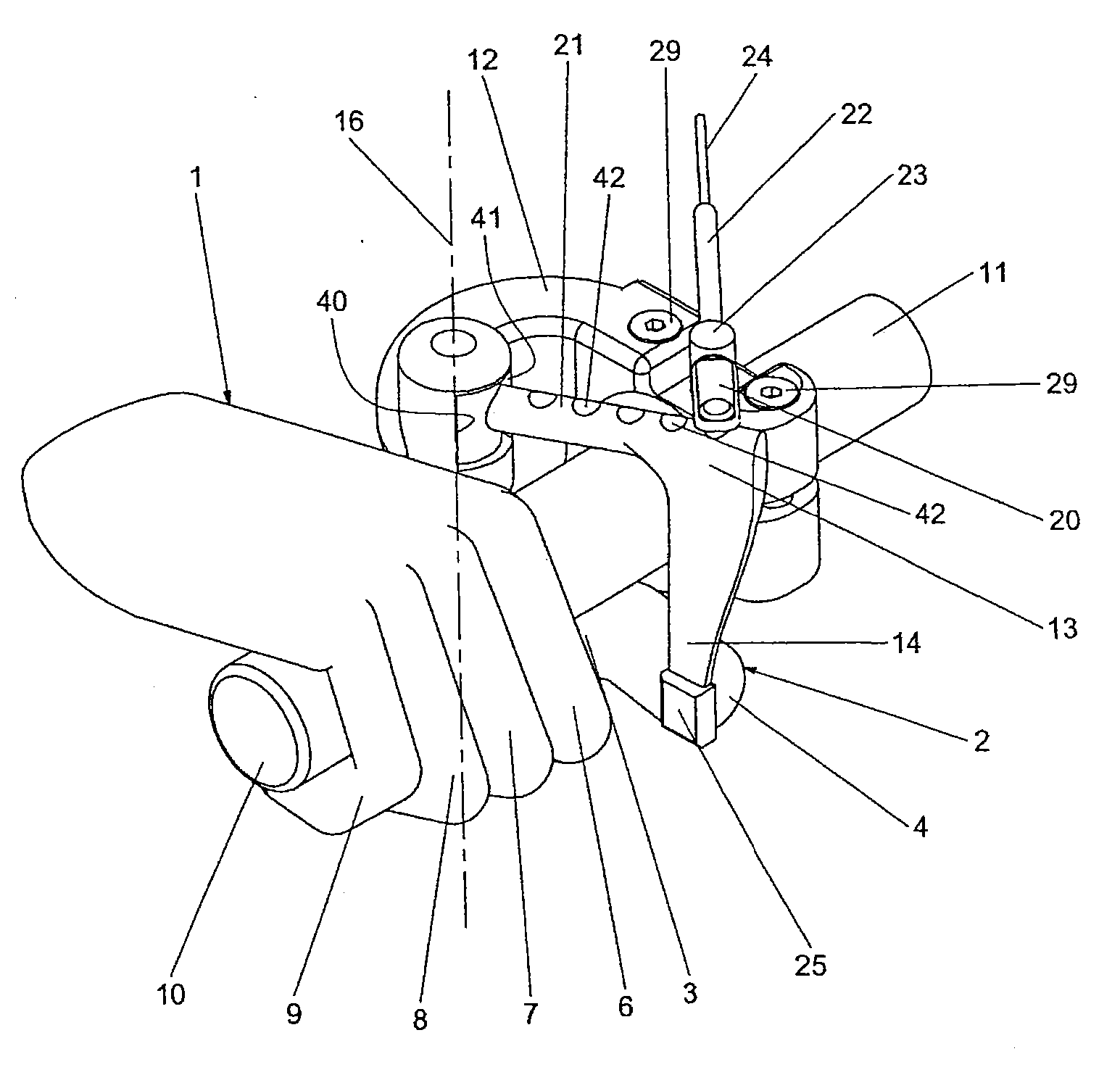
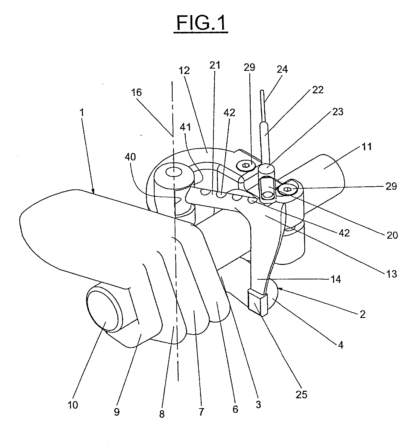
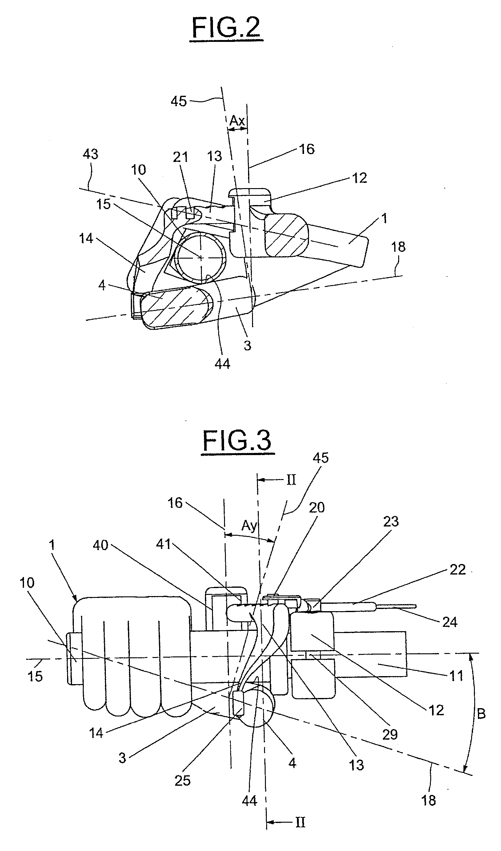
[0075]In all the figures, the references bearing the same numbers relate to corresponding elements having similar functions. As illustrated in FIGS. 1 to 5, the device comprises a handle 10, grasped by a hand 1 and clutched by the index finger 6, the middle finger 7, the ring finger 8 and the little finger 9. The thumb 2 is for its part placed under the handle 10, its proximal phalanx 3 resting on the latter, thereby gripping it. The handle 10 is fixed to a handle support 11. The handle support 11 may be a handlebar or a steering wheel.

[0076]A trigger support 12 is fixed to the handle support 11 thanks to two screws 29. A trigger 13 can be moved on the trigger support 12 by articulating about a virtual axis 16 close to the articulation of the thumb 5. This trigger 13 is furnished with attachments 21 onto one of which a connecting part 20 is attached. A cable 24 allowing the operation of a controlled system is fixed to this connecting part 20 and slides in a sleeve 22, attached to th...

second embodiment

[0102]With the aid of FIGS. 8 to 10, the second embodiment will now be described. A trigger 50 is attached to the trigger support 12 and can be moved in rotation about an axis 51.

[0103]As illustrated in FIGS. 9 and 10, the axis of rotation 51 is no longer close to the normal 45 to the reference plane 18 as in the first embodiment, but substantially parallel to the latter. A return system 28 allows the trigger 13 to return to a rest position.

[0104]The return means 28 comprises a spring bearing on a protrusion 52 at a point distant from the axis of rotation 51. A connecting part 53 connects the protrusion 52 to a piston 30 which, during a travel 19, will generate a pressure in order to operate the controlled system. The proximal phalanx / distal phalanx reference plane 18 is in this instance substantially parallel to the axis 15 of the handle.

[0105]It is also possible to use another type of return system, such as for example a hydraulic or pneumatic system which does not necessarily use...

third embodiment

[0107]In the third embodiment, illustrated in FIG. 11, a trigger 60 moves in translation relative to the trigger support 12 thanks to two guides 35. The end 14 of the trigger moves parallel to the axis 15 of the handle 10.

[0108]Because of the sliding of the lateral side 44 of the proximal phalanx 3 along a bearing surface 46 of the handle 10, the internal face of the end of the distal phalanx follows the movement of the end 14 of the trigger 13 with a reduced relative sliding action. A return spring 61 is attached between the trigger 60 and the trigger support 12.

[0109]A linear position sensor 62 without contact is attached to the trigger support 12 and informs a real time system on the position of the trigger 13 so that the latter operates the controlled system.

[0110]In a variant, the movement of the trigger may very well be a combination of a rotation about an axis and a translation, described above, in order to best adapt to the preferences of the user.

[0111]The fourth embodiment...


PUM


Abstract

A manual control device including a handle configured to be grasped by a hand with a thumb, and a trigger configured to be subjected to a pressure from the distal phalanx of the thumb. The trigger is placed relative to the handle so as to be able to be subjected to a pressure from the distal phalanx while the proximal phalanx from the thumb is resting along the handle.

Description

CROSS-REFERENCE OF RELATED APPLICATIONS[0001]This application is a divisional application of application Ser. No. 12 / 446,247 filed Apr. 20, 2009, the entire contents of which is incorporated herein by reference. application Ser. No. 12 / 446,247 which is a National Stage of PCT / FR07 / 052194 filed Oct. 17, 2007, and claims the benefit of priority under 35 U.S.C.§119 of French Application 069161 filed Oct. 19, 2006.BACKGROUND OF THE INVENTION[0002]1. Field of the Invention[0003]The present invention relates to the field of devices for manually controlling a machine, coupled with a handle making it possible to grasp the machine. In particular, the device makes it possible to control sensitively and without fatigue a control device of one of the controlled systems of this machine.[0004]2. Description of the Related Art[0005]A considerable grasping force with the hand on the handle of a machine is usually necessary to allow a correct holding of the machine and its use in total safety. It is...

Claims


Application Information

Patent Timeline
Patent Type & Authority Applications(United States)
IPC IPC(8): G05G1/04
CPCB62K23/06Y10T74/20612Y10T74/2028Y10T74/20396Y10T74/20438
Inventor VELLUTINI, FREDERIC
Owner VELLUTINI FREDERIC
Why Eureka
Try Eureka