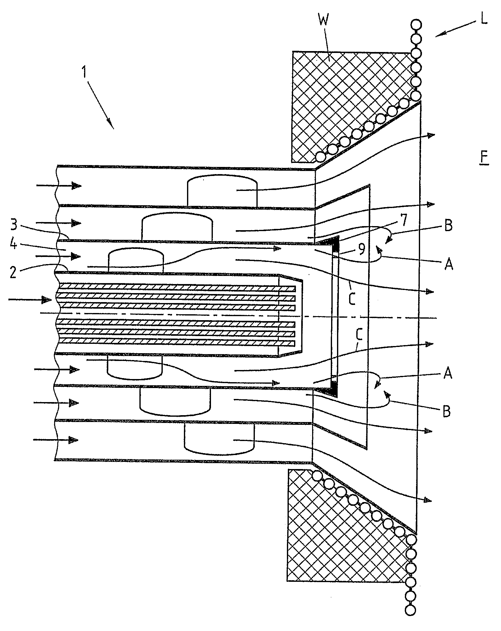
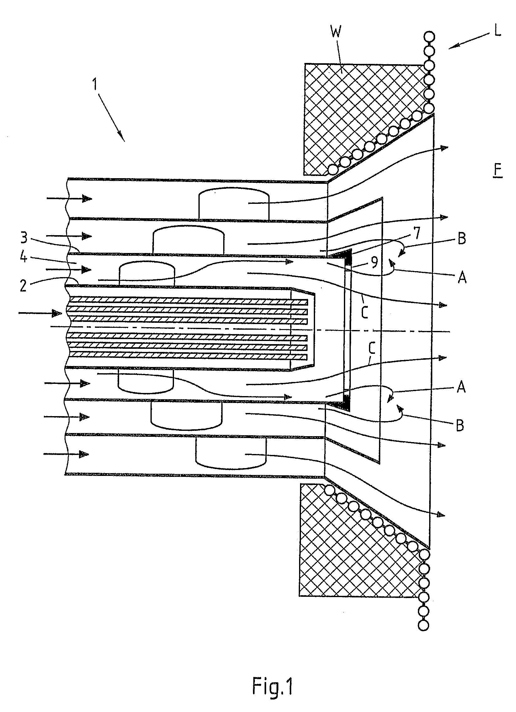
[0012]The invention recognised that the drawback of an increased carrying air quantity and larger particle diameters in the combustion of coarse-grain fuels, such as biomass, can be in any case partially compensated by a fluidic deflection of a part of the primary air in the direction of the core zone of the burner mouth. The deflection makes it possible to guide a part of the primary air around the
flame-holder or to guide it centrally through the latter, without this part of the primary air arriving in the turbulent
particle flow zone adjoining the
flame-holder. This only takes place at a later point in time, at which the turbulent
particle flow zone has widened and the volatile components of the fuel particles have escaped to a greater extent. The particle concentration is consequently high in the
particle flow downstream of the
flame-holder. Consequently, the flame of the burner can be stabilised despite a delayed escape of volatile components. In addition, the
oxygen concentration in the particle flow downstream of the flame-holder is clearly sub-stoichiometric, which counteracts the formation of
nitrogen oxides.
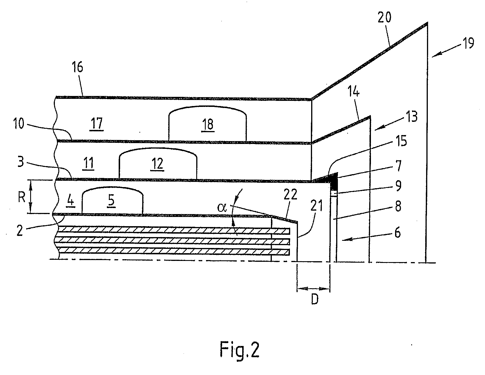
[0018]Alternatively or in addition, the core tube may taper toward its outlet-side end. The tapering of the end of the tube, compared to an abrupt end of the core tube, has the
advantage that the flow can be guided more uniformly. Stalling and turbulences can thus be avoided in the region of the inner part of the primary air flow. It is particularly preferred if a tapering of the core tube is accompanied by a longitudinal-side spacing of the flame-holder or opening of the primary tube, on the one hand, and the outlet-side end of the core tube, on the other hand.
[0023]Provided between the core tube and the deflection device is preferably a flow channel, through which the deflected primary air flow is guided. In this case, it is particularly preferred from the technical flow point of view if the
free flow cross section in the flow channel of the deflection device remains constant. An unfavourable variation with respect to energy of the flow speed can thus be avoided.
[0026]The at least one flow director may, as an alternative thereto, also be oriented transverse to the longitudinal direction, i.e. partially in the
peripheral direction, of the primary tube. In this case, the orientation of the at least one flow director may differ from an orientation in the longitudinal direction of the primary tube in such a way that the swirl of the primary air flow is intensified by the at least one flow director, at least for a part of the primary air flow close to the core tube. The at least one flow director may, however, also reduce the swirl of the primary air flow in an also possible orientation pointing more in the longitudinal direction of the primary tube. The at least one flow director may, however, also be oriented in the opposite direction to the swirl direction of the primary air flow. This may, for example, lead to the fact that the swirl direction of the primary air flow is reversed at least for a part of the primary air flow close to the core tube. In order to intensify the swirl of the primary air flow in regions, it may be expedient to incline the at least one flow director by 35° to 45° relative to the longitudinal direction of the primary tube. In order to weaken the swirl of the primary air flow in regions, it may be favourable to incline the at least one flow director by less than 25°, in particular less than 15°, relative to the longitudinal direction of the primary tube.
[0027]Depending on the boundary conditions in terms of flow technology, each of these orientations of the at least one flow director may entail positive effects. Basically, by means of a swirl, which has a different strength or is differently directed, of parts of the primary air flow, a separation in terms of flow technology of these parts can be achieved, as the latter have different properties in terms of flow technology. To enable a control of the burner, the at least one flow director may be variable with regard to its orientation, i.e. incline compared to the core tube.
[0029]Moreover, it can easily be achieved that the swirl of the outer flow in the primary tube gap remains uninfluenced by the at least one flow director in order to not impair the flame stability. For this purpose, the flow director is not provided in the last outer 20% of the primary tube gap. If the outer 30% or even 40% of the primary tube gap can be kept free of flow directors, this is favoured in terms of flow technology. The outer flow director-free region may, for example, be increased in that the number of flow directors arranged on the
peripheral side is increased.

