Method and apparatus for securing a programmable device using a kill switch

a programmable device and kill switch technology, applied in the direction of unauthorized memory use protection, instruments, pulse techniques, etc., can solve the problems of least part of the device to be reset, disabled,

Active Publication Date: 2012-11-01
ALTERA CORP
View PDF11 Cites 18 Cited by
  • Summary
  • Abstract
  • Description
  • Claims
  • Application Information

AI Technical Summary

Benefits of technology

[0003]The present disclosure relates to securing programmable devices (e.g., programmable logic devices (PLDSs)) using a kill switch. A kill switch may be implemented using, for example, a kill fuse, a non-volatile memory bit, or a volatile battery-backed memory bit. In response to a detected security threat, for example, the kill switch may be blown, causing at least part of the device to be reset, disabled, or both. In some embodiments, the device's configuration circuitry and / or decryption circuitry is permanently disabled in response to a detected security threat.

Problems solved by technology

In response to a detected security threat, for example, the kill switch may be blown, causing at least part of the device to be reset, disabled, or both.

Method used


Image

  • Method and apparatus for securing a programmable device using a kill switch
  • Method and apparatus for securing a programmable device using a kill switch
  • Method and apparatus for securing a programmable device using a kill switch

Examples


Embodiment Construction

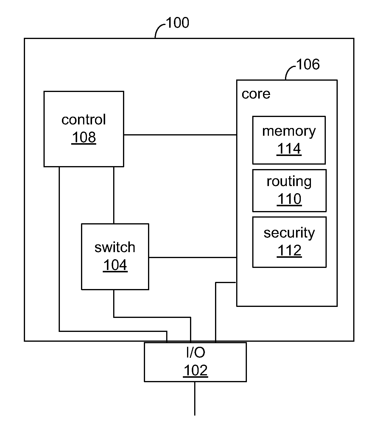
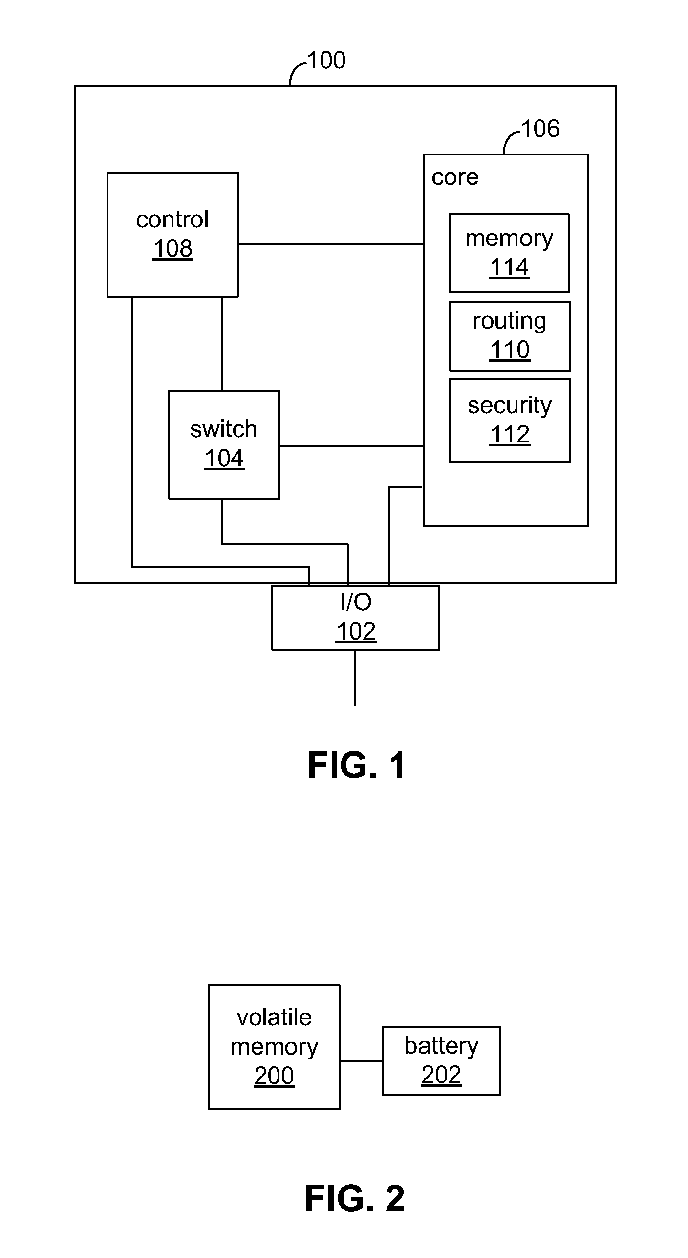
[0010]FIG. 1 shows an illustrative programmable logic device (PLD) 100 as an example of a programmable device in which the present disclosure may be implemented. It will be understood that the present disclosure may be applied to any suitable programmable device, including field programmable gate array (FPGA) devices or any other type of PLDs. PLD 100 may include core configuration fabric 106, which may include any suitable software, circuitry, or both for storing and implementing a user design in PLD 100. This may include, for example, any suitable programmable logic implemented using any suitable technology for memory (e.g., configuration RAM (CRAM)) and programmable logic (e.g., logic array blocks), digital signal processing (DSP) circuitry with hard-wired logic (e.g., multiply-accumulate circuits), any other suitable hardware, software, or both, or any combination thereof. SRAM, for example may be used to store configuration data.

[0011]I / O circuitry 102 may include one or more p...


PUM


Abstract

A kill switch is provided that, when triggered, may cause the programmable logic device (PLD) to become at least partially reset, disabled, or both. The kill switch may be implemented as a fuse or a volatile battery-backed memory bit. When, for example, a security threat is detected, the switch may be blown, and a reconfiguration of the device initiated in order to zero or clear some or all of the memory and programmable logic of the PLD.

Description

BACKGROUND OF THE DISCLOSURE[0001]Programmable logic devices that store their configuration data in static random access memory (“SRAM”) storage are prevalent. SRAM storage is volatile; it does not retain its contents when power is lost. Therefore, programmable logic devices based on SRAM technology are used with nonvolatile storage, to retain the configuration programming data during times that the device is switched off or otherwise not provided with power. However, a competitor may monitor the data flowing out of the nonvolatile storage on power-up, and thereby determine the programming configuration of the programmable logic device. Indeed, the competitor need not even analyze the data stream, but need only record it and store it in its own devices.[0002]Some devices that store configuration programming data in nonvolatile memory components have security features (e.g., encryption / decryption) to protect sensitive data. Unfortunately, an unauthorized user may sometimes circumvent...

Claims


Application Information

Patent Timeline
Patent Type & Authority Applications(United States)
IPC IPC(8): H03K19/003
CPCG06F21/554G06F2221/2143G06F21/76G06F21/75G06F21/755
Inventor PEDERSEN, BRUCE B.REESE, DIRK A.JOYCE, JUJU
Owner ALTERA CORP
Why Eureka
Try Eureka