Light Diffusing Fibers and Methods for Making the Same

a technology of light diffusing fibers and optical fibers, which is applied in the direction of glass optical fibers, lighting and heating apparatus, instruments, etc., can solve the problems of easy attenuation of light propagating through such fibers, and the intensity of light emitted from such fibers decreases with the length of the fiber

Inactive Publication Date: 2012-11-01
CORNING INC
View PDF1 Cites 77 Cited by
  • Summary
  • Abstract
  • Description
  • Claims
  • Application Information

AI Technical Summary

Problems solved by technology

However, light propagating through such fibers is readily attenuated and, as a result, the intensity of the light emitted from the fiber decreases with the length of the fiber.

Method used


Image

  • Light Diffusing Fibers and Methods for Making the Same
  • Light Diffusing Fibers and Methods for Making the Same
  • Light Diffusing Fibers and Methods for Making the Same

Examples


examples

[0070]The invention will be further understood by reference to the following examples.

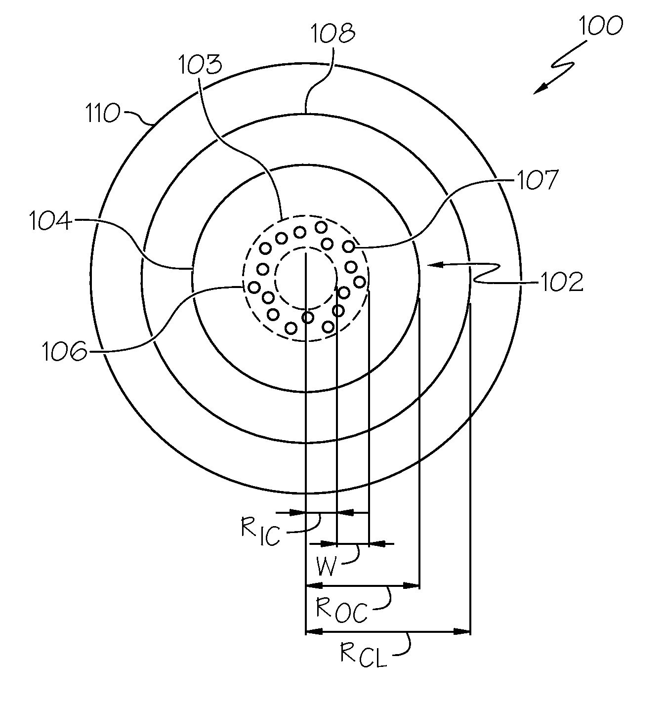
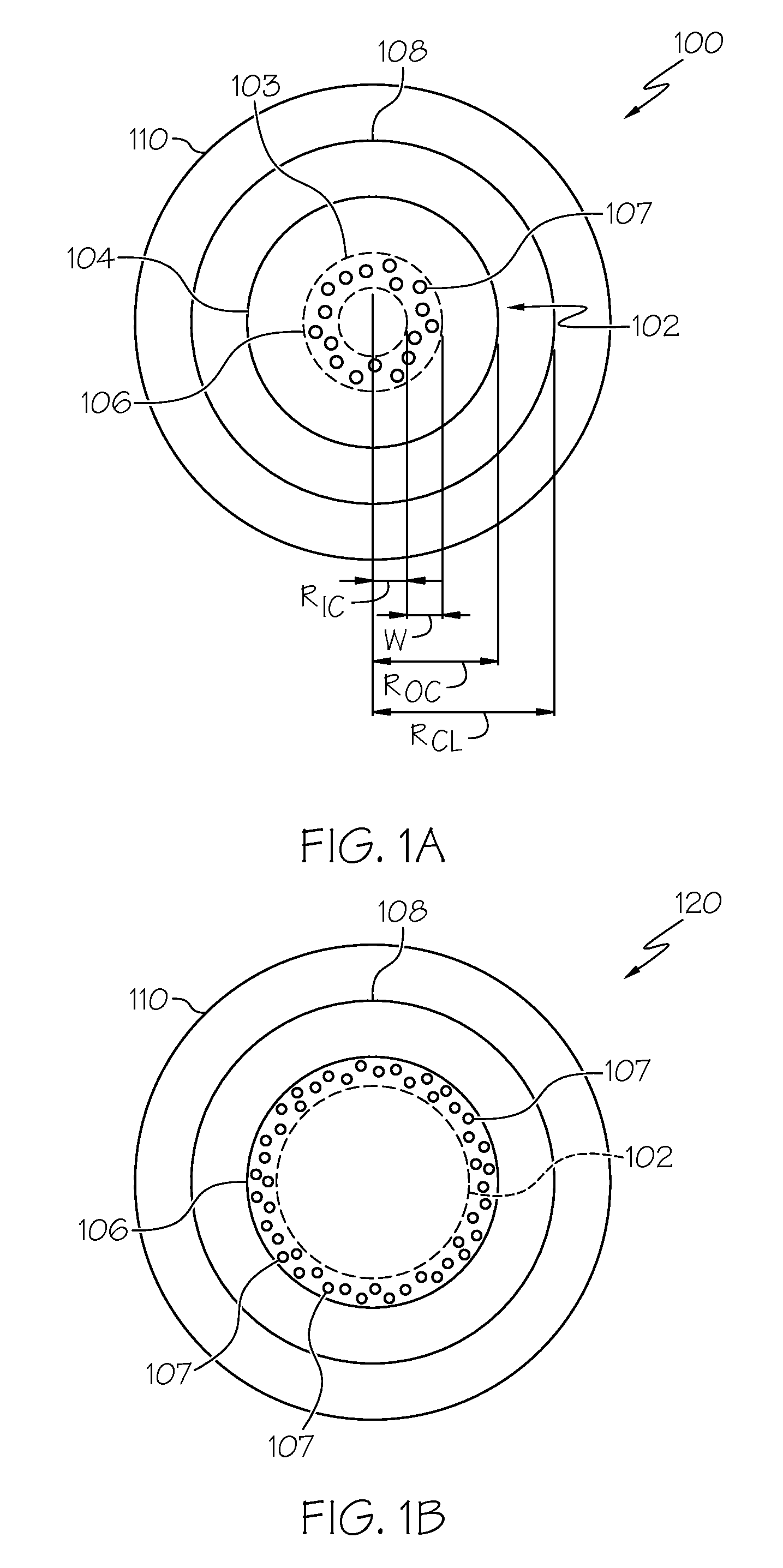
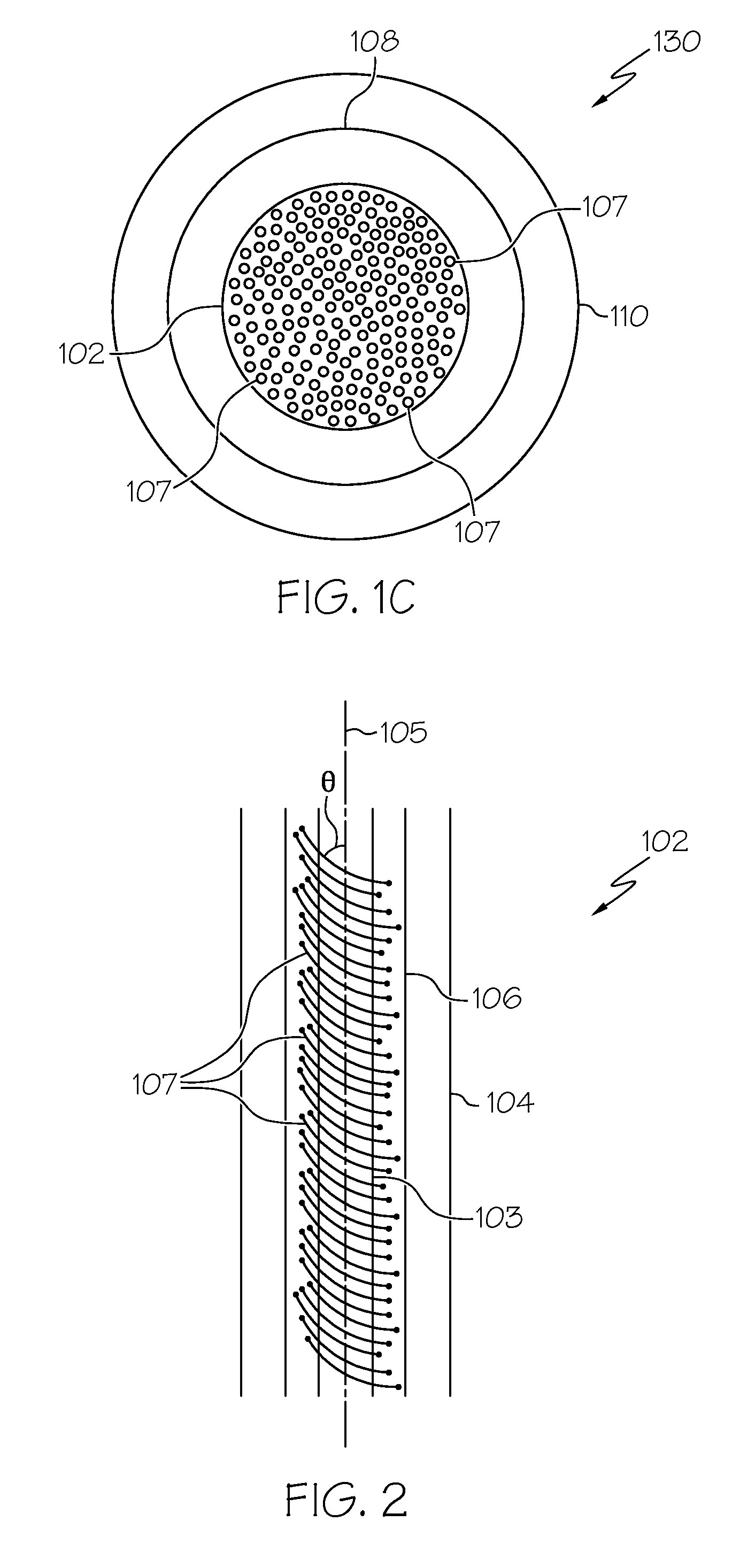
[0071]Three 1 meter samples of light diffusing optical fiber were prepared from an optical fiber having a relative refractive index profile similar to that shown in FIG. 5. The fiber had a 125 μm glass core, a low index polymer cladding having a radial thickness of 20 μm, and a secondary coating having a 60 μm radial thickness. Comparative sample 1 was measured in its “as formed” condition (i.e., without the formation of helical voids). Sample 2 was formed with helical voids having a pitch of 0.20 m and sample 3 was formed with helical voids having a pitch of 0.1 m. A range of wavelengths from about 400 nm to about 1200 nm were coupled into the input end of each fiber and the intensity of the light coupled through to the output end was measured over the range of wavelengths. The light source was a white light tungsten lamp-based fiber source. Detection of the light coupled through the fiber was mea...


PUM

PropertyMeasurementUnit
radial thicknessaaaaaaaaaa
diameteraaaaaaaaaa
axial lengthaaaaaaaaaa

Abstract

Light diffusing optical fibers and methods for producing light diffusing optical fibers are disclosed. In one embodiment, a light diffusing optical fiber includes a core portion formed from silica glass and comprising a plurality of helical void randomly distributed in the core portion of the optical fiber and wrapped around the long axis of the optical fiber. A pitch of the helical voids may vary along the axial length of the light diffusing optical fiber in order to achieve the desired illumination along the length of the optical fiber. A cladding may surround the core portion. Light guided by the core portion is scattered by the helical voids radially outward, through the cladding, such that the light diffusing optical fiber emits light with a predetermined intensity over an axial length of the light diffusing optical fiber, the light diffusing optical fiber having a scattering induced attenuation loss greater than about 0.2 dB/m at a wavelength of 550 nm.

Description

BACKGROUND[0001]1. Field[0002]The present specification generally relates to light diffusing optical fibers for use in illumination applications and, more specifically, to light diffusing optical fibers in which a plurality of helical voids are randomly distributed in the core portion of the fiber to increase scattering induced attenuation losses along the length of the fiber. Methods for making such fibers are also disclosed.[0003]2. Technical Background[0004]Bend insensitive optical fibers may be produced by introducing a random air-line ring into a glass portion of the optical fiber which allows the fiber to be bent to a small diameter without significant attenuation of an optical signal passing through the fiber. The air lines (which are actually gas-filled voids) formed in the fiber generally extend parallel to the long axis of the fiber. Such fibers are structurally similar to standard communication fibers.[0005]Random air-line technology has also been utilized to produce ligh...

Claims


Application Information

Patent Timeline
Patent Type & Authority Applications(United States)
IPC IPC(8): G02B5/02B29D11/00B05D5/06
CPCG02B6/001G02B6/02295G02B6/02309G02B6/02395G02B6/03644B82Y30/00G02B6/03627
Inventor BUTTON, LESLIE JAMESKOBYAKOV, ANDREYKUCHINSKY, SERGEY ANATOLYEVUCHLOGUNOV, STEPHAN LVOVICHZAKHARIAN, ARAMAIS
Owner CORNING INC
Why Eureka
Try Eureka