Moving picture coding method, apparatus, program, and integrated circuit

Inactive Publication Date: 2012-11-01
PANASONIC CORP
View PDF4 Cites 16 Cited by
  • Summary
  • Abstract
  • Description
  • Claims
  • Application Information

AI Technical Summary

Benefits of technology

[0043]According to the present invention, as shown in FIG. 5, it is possible to disable a motion search function in the P-slices located above the I-slice without performing complex processing of dynamically limiting motion search ranges. Decoding I-slices in following pictures while performing such simple processing makes it possible to properly decode a picture having a degradation-free image quality even when some part of the stream has been lost during transmission via a network. Here, a first P-slice region is located at the bottom portion of the refreshed region adjacent to the I-slice in a direction opposite to the forward direction for the shift. This bottom p

Problems solved by technology

However, it is unrealistic to directly process a huge amount of information digitally using the above-described conventional information media because, when calculating the data amount of each information medium described above as digital data amount, data amount per character is 1 to 2 bytes while that of sound per second is not less than 64 K bits (telephone speech quality) and that of moving pictures per second is not less than 100 M bits (present TV receiving quality).
However, it is impossible to transmit, using ISDN, moving pictures of TV camera as they are, that is, uncompressed moving pictures.
When coded image data that is a stream is transmitted via a network, the stream may be partly lost due to network congestion or the like.
In the case where the stream is partly lost, a receiving side cannot correctly decode the image corresponding to the lost (part of) stream.
Thus, the image quality degrades.
However, even if a picture is decoded properly in all units of a slice, all the decoded pixels of the picture are not a

Method used


Image

  • Moving picture coding method, apparatus, program, and integrated circuit
  • Moving picture coding method, apparatus, program, and integrated circuit
  • Moving picture coding method, apparatus, program, and integrated circuit

Examples


embodiment 2

(Structure)

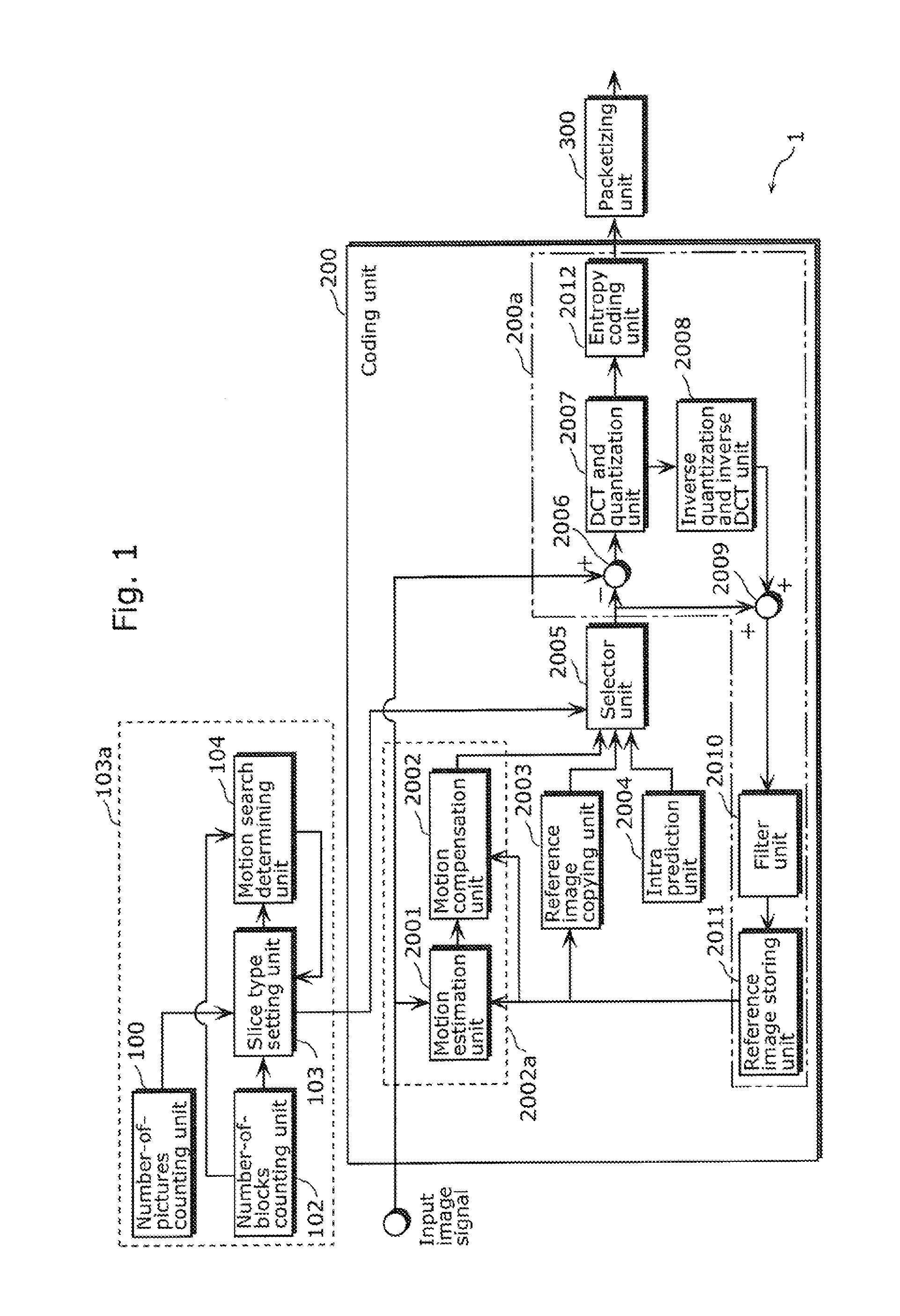
[0209]FIG. 7 is a block diagram showing a structure of a moving picture coding apparatus 1A in Embodiment 2 according to the present invention. The same descriptions about the same structural elements as those of the moving picture coding apparatus 1 in Embodiment 1 are not repeated in the following descriptions,

[0210]In the case where a transmission error occurs, a number-of-cycles-of-slice-insertion setting unit 105 (for example, an element of a selecting unit 105x (FIG. 28)) determines the number of cycles of I-slice insertion performed by the moving picture coding apparatus 1A so that the moving picture coding apparatus 1A performs picture refresh for prevention of propagation of image quality degradation. Next, the number-of-cycles-of-slice-insertion setting unit 105 notifies each of a slice type setting unit 103 and a motion search determining unit 104 of the determined number of cycles of slice insertion. The number-of-cycles-of-slice-insertion setting unit 105 mak...

embodiment 3

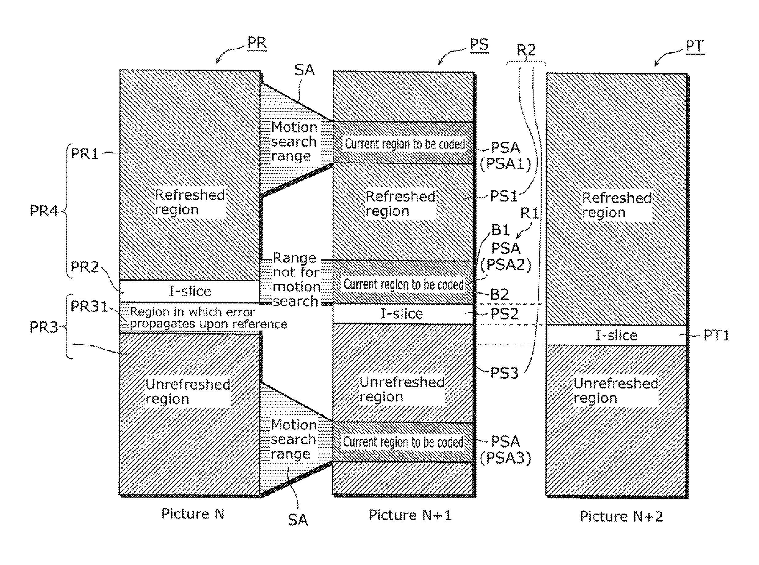
[0226]An moving image coding method according to Embodiment 3 includes a first coding process of performing inter coding without using any motion vectors on each of first P-slices (NoMC-P-slices 42Aa and 42Ab) included in a first region (the first region R1 in FIG. 19). In this first coding process, the maximum value for the size of each of the first P-slices (NoMC-P-slices 42Aa and 42Ab) is smaller than the maximum value for the size (the size of the MC-P-slice 43 in FIG. 19) of second P-slices (MC-P-slices 43 and 44 in FIG. 19).

[0227]Here, the maximum value for the size (for example, the size of the NoMC-P-slice 42Aa) of the first P-slice (NoMC-P-slice 42A) may be larger than the size of the I-slice (I-slice 41 in FIG. 19) in the picture (picture PS in FIG. 19) including the first P-slices (NoMC-P-slices 42Aa and 42Ab) having the size corresponding to the maximum value.

[0228]Each of FIG. 11 to FIG. 13 is a diagram for illustrating Embodiment 3.

[0229]The moving image coding apparat...

embodiment 4

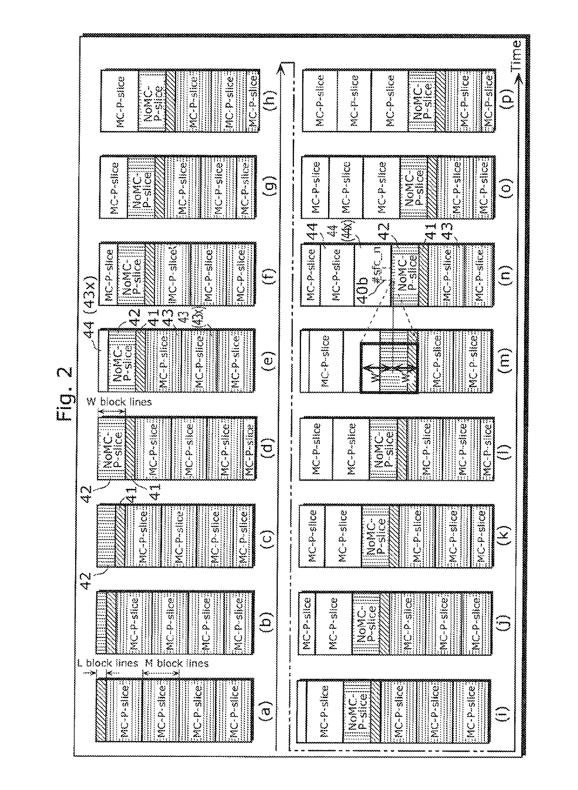
[0249]A moving picture coding method in Embodiment 4 is intended to code each of a first picture (the picture (i) in FIG. 17) that includes an I-slice and P-slices and is at a first time point (for example, at the time point of (i) in FIG. 17) and a second picture (the picture (k) in FIG. 17) that includes an I-slice and P-slices and is at a time point (for example, at the time point for (k) in FIG. 17) that is later than the first time point, and further code a third picture (the picture (j) in FIG. 17) that does not include any I-slice and is at a time point (the time point for (j)) between the first time point and the second time point.

[0250]Here, for example, in the moving picture coding method, the third picture ((j) in FIG. 17) may include a region R3 including both a first region (a NoMC-P-slice 42 region in (i) in FIG. 17, a first region R1) and an I-slice region (I-slice PR2 in (i) in FIG. 17) in the first picture ((j) in FIG. 17). In addition, the first coding process (per...


PUM


Abstract

A moving picture coding method in which the position of a current I-slice for a current picture is shifted in the vertical direction of the current picture, and which includes (i) performing inter coding on a first P-slice without using a motion vector (Sa1), and (ii) performing intra coding on a second P-slice using a motion vector (Sa2); the first P-slice is included in a first region that is adjacent to the current I-slice in the direction opposite to the forward direction for the shift in the vertical direction, and the second P-slice is included in a second region that is other than the first region within the current picture.

Description

TECHNICAL FIELD[0001]The present invention relates to moving picture coding methods and moving picture coding apparatuses. The present invention particularly relates to moving picture coding methods and moving picture coding apparatuses for dividing an image signal into slices including plural blocks, and coding each of the slices in units of a block according to the MPEG-(Moving Picture Experts Group) 4 AVC standard (also called as ITU-T H.264 standard).BACKGROUND ART[0002]Recently, the multi-media era has come in which sound, pictures and other pixel values are integrated into one media, and conventional information media as communication tools like newspapers, magazines, TV, radio and telephone are regarded as the targets of multi-media. Generally, multi-media is a form of simultaneous representation of not only characters but also graphics, sound, and especially pictures. In order to handle the above-described conventional information media as multi-media, it is a requisite to r...

Claims


Application Information

Patent Timeline
IPC IPC(8): H04N7/32H04N7/28H04N19/94
CPCH04N19/61H04N19/174H04N19/107
Inventor KADONO, SHINYAOZEKI, HIDEKATSUMAMIYA, YASUHIRO
Owner PANASONIC CORP
Why Eureka
Try Eureka