Passing from a non-synchronized state between an engine and a rotor to a synchronized state

a technology of synchronization and rotor, which is applied in the direction of engine control, analog and hybrid computing, engine control, etc., can solve the problems of rotor deceleration, damage to the engine turbine, and pitch giving rise to an increase in the lift of the main rotor and also to an increase in the aerodynamic drag. , to achieve the effect of reducing the impact of the free-wheel

Active Publication Date: 2012-11-01
EUROCOPTER
View PDF4 Cites 2 Cited by
  • Summary
  • Abstract
  • Description
  • Claims
  • Application Information

AI Technical Summary

Benefits of technology

[0035]The present invention is defined by the claims. It provides a regulation method and an associated device for at least one aeroengine in order to reduce impacts in the free-wheel during resynchronization of the engine and the main gearbox.

Problems solved by technology

An increase in pitch tends to cause the main rotor to decelerate, the increase in pitch giving rise to an increase in the lift from the main rotor and also to an increase in its aerodynamic drag.
One consequence of this phenomenon is overheating in the combustion chamber of the engine, which can lead to damage to a turbine of the engine.
Conversely, the third speed of rotation NR of the main rotor drops suddenly as a result of the increase in collective pitch, thereby leading to an increase in the drag of said main rotor.

Method used


Image

  • Passing from a non-synchronized state between an engine and a rotor to a synchronized state
  • Passing from a non-synchronized state between an engine and a rotor to a synchronized state
  • Passing from a non-synchronized state between an engine and a rotor to a synchronized state

Examples


Embodiment Construction

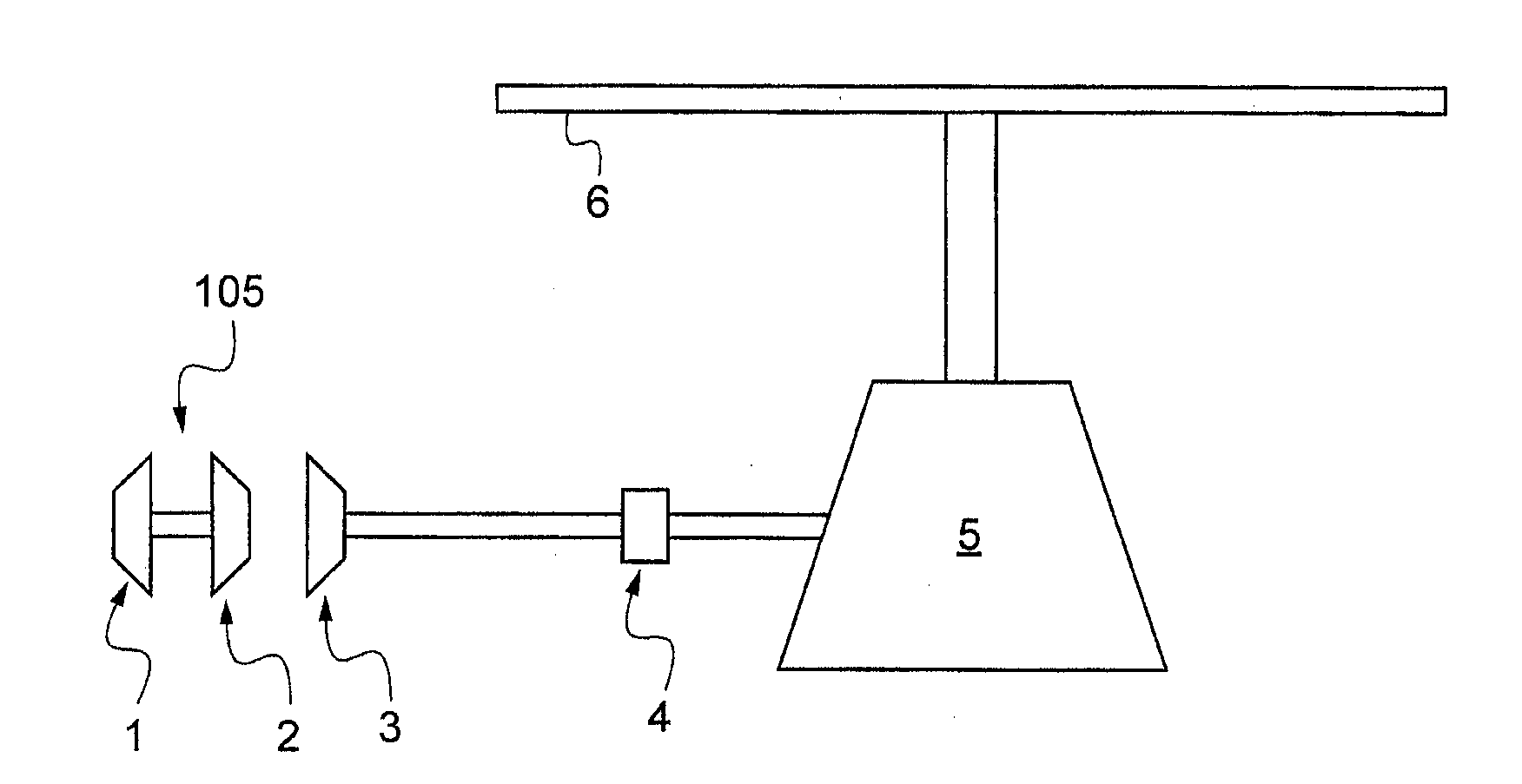
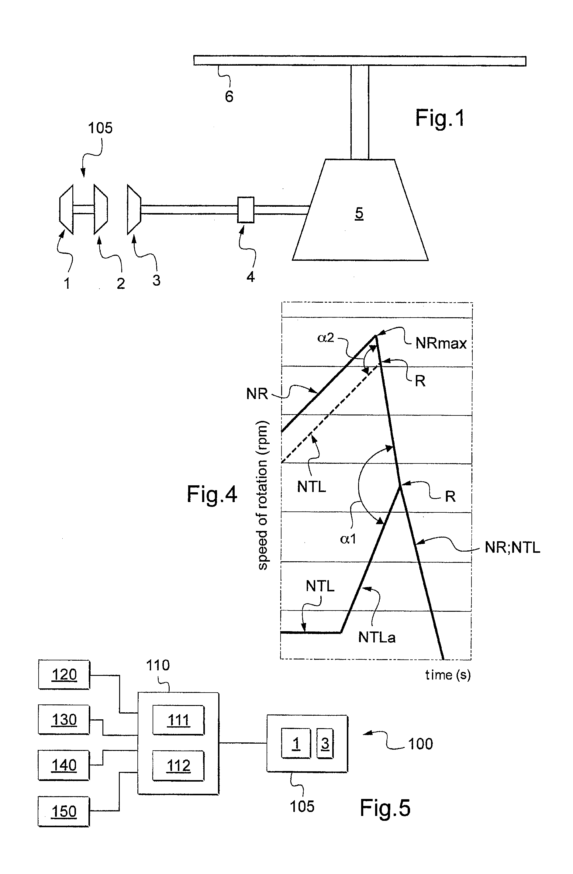
[0073]FIG. 1 is a diagram of a mechanical transmission system of a helicopter to which the method in accordance with the invention is applied.

[0074]The transmission system comprises a power plant 105 including in particular a gas generator having a compressor 1, and a high pressure turbine 2, also known as a linked turbine.

[0075]A stream of gas delivered by the high pressure turbine 2 sets the free turbine 3 of the power plant into rotation. Thus, the free turbine 3 rotates at a first speed of rotation NTL, while the gas generator and in particular its compressor rotate at a second speed of rotation NG.

[0076]In addition, the free turbine 3 is connected to a main gearbox 5 via an overrunning clutch mechanism 4, referred to more simply as a free-wheel 4.

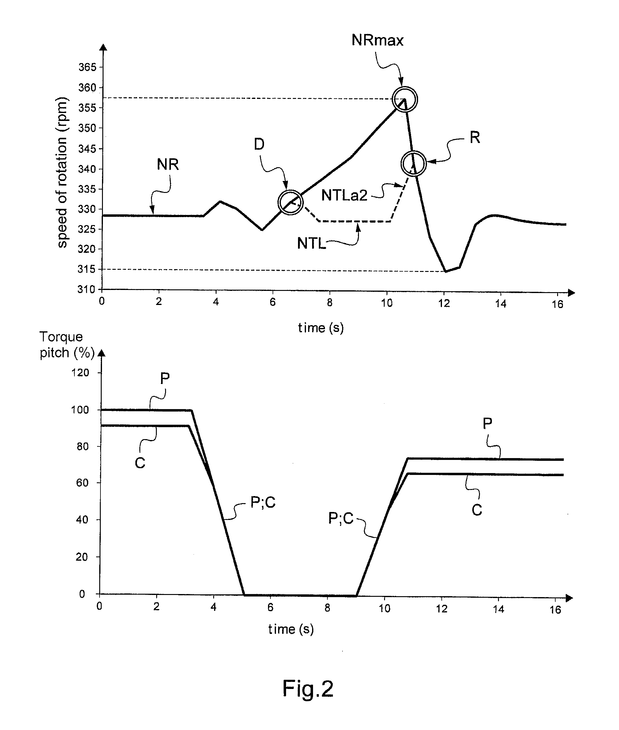
[0077]The main gearbox 5 rotates a rotary wing at a third speed of rotation NR, the rotary wing being provided with a main lift rotor 6 having a plurality of blades.

[0078]FIG. 2 gives an example of how the third speed of rotation NR of...


PUM


Abstract

In order to regulate a power plant (105) having a gas generator (1) and a free turbine (3) to drive a rotary wing, a first speed of rotation (NTL) of the free turbine (3) is regulated on a first setpoint value (NTL*) equal either to a regulation term (NRc) or to a predetermined setpoint threshold (NTL*). The regulation term (NRc) is a function of a third speed of rotation (NR) of said rotary wing in accordance, where NRc=NR*(1−d), “d” representing a non-zero constant lying in the range 0 to 1.

Description

CROSS REFERENCE TO RELATED APPLICATION[0001]This application claims priority to French patent application No. FR 11 01327 filed on Apr. 29, 2011, the disclosure of which is incorporated in its entirety by reference herein.BACKGROUND OF THE INVENTION[0002](1). Field of the Invention[0003]The present application stems from French patent application FR 11 / 01327 filed on Apr. 29, 2011, the content of which is incorporated herein.[0004]The invention relates to the general field of regulating the engines of an aircraft, in particular of a rotary wing aircraft.[0005](2). Description of Related Art[0006]This type of aircraft generally has at least one rotor for providing lift and possibly also propulsion, which rotor has a plurality of variable-pitch blades, and the aircraft also has a power plant of the type comprising an engine driving the main rotor in rotation by means of a main gearbox known under the acronym MGB.[0007]Such an engine may be a free turbine turboshaft engine having a gas...

Claims


Application Information

Patent Timeline
Patent Type & Authority Applications(United States)
IPC IPC(8): F02C9/00
CPCG05D1/08G05D13/46G05D1/0841B64C27/14B64C27/57F02C3/10F02C9/00F05D2220/329F05D2270/304
Inventor ROSSOTTO, REGIS
Owner EUROCOPTER
Why Eureka
Try Eureka