
Positioning apparatus, exposure apparatus, and method of manufacturing device

a technology of exposure apparatus and positioning apparatus, which is applied in the direction of magnetic bodies, printers, instruments, etc., can solve the problems of affecting the accuracy of positioning, the relationship between the magnetic flux value detected with a change in the size of the gap and the force generated by the electromagnet is problematically changed, and the target force cannot be obtained upon a fluctuation in the force generated by the electromagnet, so as to prevent the effect of deterioration of positioning accuracy

Inactive Publication Date: 2012-11-08
CANON KK
View PDF2 Cites 3 Cited by
  • Summary
  • Abstract
  • Description
  • Claims
  • Application Information

AI Technical Summary

Benefits of technology

The present invention provides a way to prevent problems with positioning accuracy caused by changes in the gap between an electromagnet and an attraction target. This is done by using a sensor to detect the magnetic flux generated by the electromagnet and adjusting the magnet accordingly to compensate for any errors. This results in a more accurate positioning system.

Problems solved by technology

However, in such a control method, even if the coil current value remains the same, the force varies in the course of increasing / decreasing the current value, due to the influence of the magnetic hysteresis of an electromagnet core.
When the force of the electromagnet is controlled by controlling the magnetic flux value, the relationship between the magnetic flux value detected with a change in size of the gap and the force generated by the electromagnet problematically changes.
That is, even if the magnetic flux value is controlled in accordance with the command value, a target force cannot be obtained upon a fluctuation in force generated by the electromagnet due to a change in size of the gap.

Method used


Image

  • Positioning apparatus, exposure apparatus, and method of manufacturing device
  • Positioning apparatus, exposure apparatus, and method of manufacturing device
  • Positioning apparatus, exposure apparatus, and method of manufacturing device

Examples


Embodiment Construction

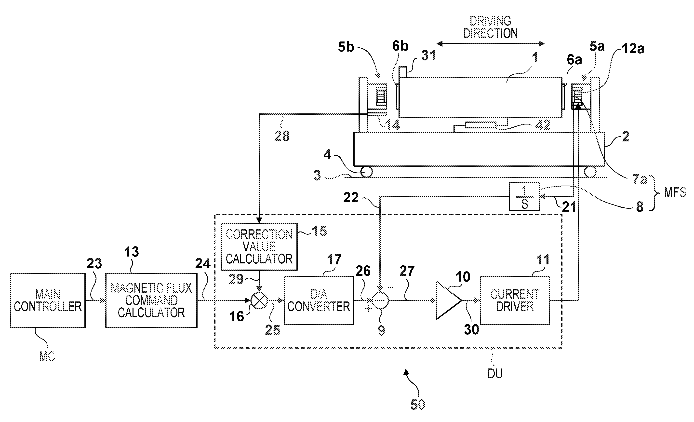
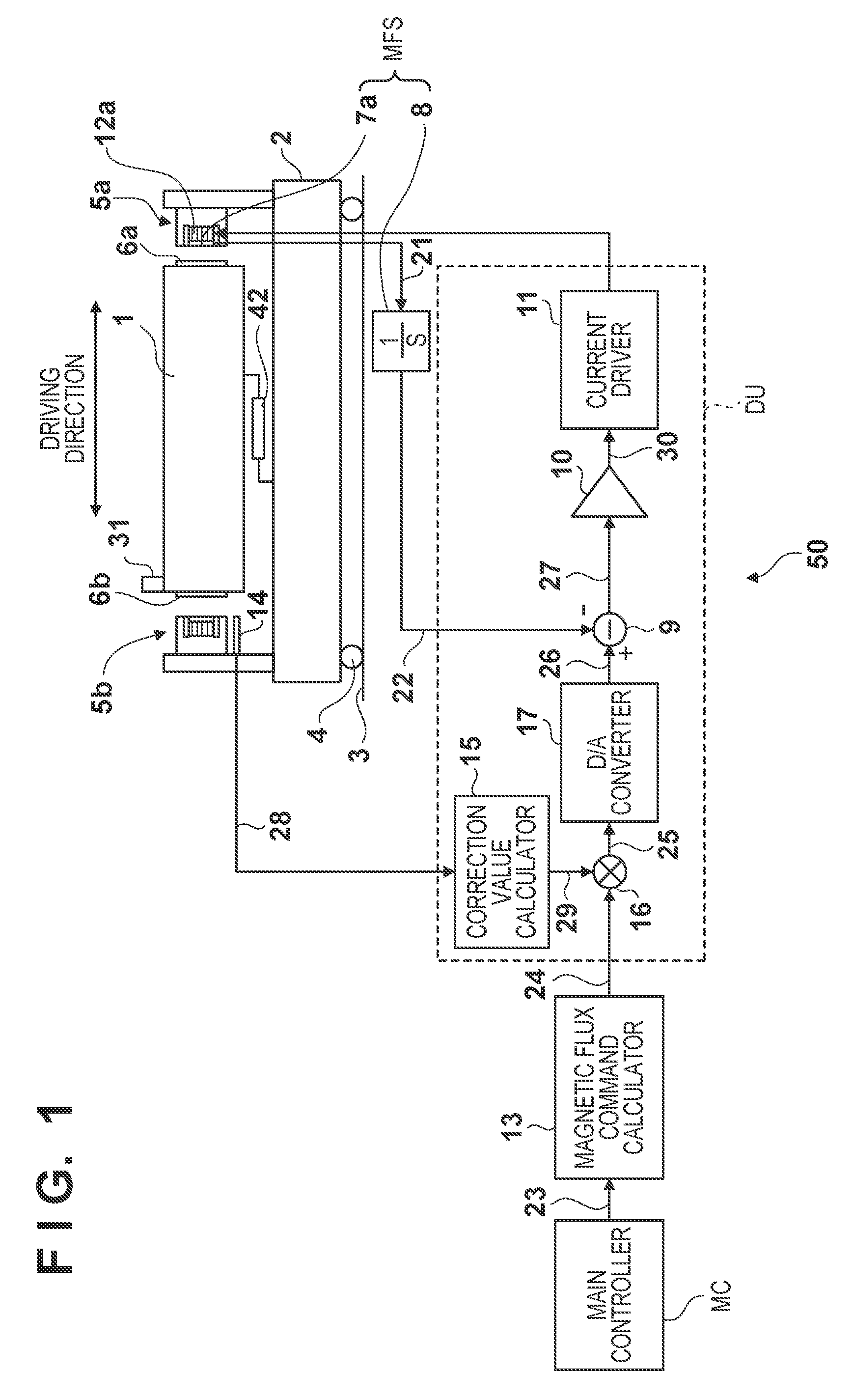
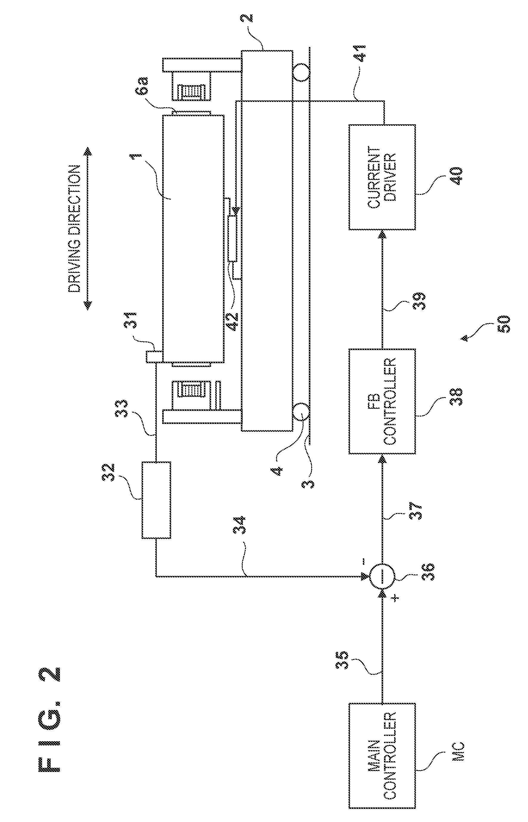
[0016]The configuration and operation of a positioning apparatus 50 according to an embodiment of the present invention will be described with reference to FIGS. 1 and 2. The positioning apparatus 50 includes a feedforward control system which performs feedforward control of a force applied to a fine moving stage 1 serving as an object to be positioned, and a feedback control system which performs feedback control of the position of the fine moving stage 1. FIG. 1 is a block diagram showing the feedforward control system in the positioning apparatus 50, and FIG. 2 is a block diagram showing the feedback control system in the positioning apparatus 50. The positioning apparatus 50 is applicable to, for example, at least one of an original stage mechanism which positions an original and a substrate positioning mechanism which positions a substrate in an exposure apparatus which transfers the pattern of the original onto the substrate.

[0017]The positioning apparatus 50 can include a coa...


PUM


Abstract

A positioning apparatus controls a relative position between a first member and a second member. The apparatus includes an electromagnet fixed to the first member, an attraction target fixed to the second member so as to be attracted by the electromagnet, a magnetic flux sensor which detects a magnetic flux value generated by the electromagnet, and a driving unit which drives the electromagnet in accordance with an error between the magnetic flux value detected by the magnetic flux sensor and a corrected magnetic flux command value obtained by correcting a magnetic flux command value in accordance with a size of a gap between the electromagnet and the attraction target.

Description

BACKGROUND OF THE INVENTION[0001]1. Field of the Invention[0002]The present invention relates to a positioning apparatus, an exposure apparatus, and a method of manufacturing a device.[0003]2. Description of the Related Art[0004]In an exposure apparatus which manufactures a device such as a semiconductor device, a substrate stage mechanism and an original stage mechanism are required to achieve moving stages at a high acceleration and a high speed, and positioning these stages with high accuracy. It is common practice to employ a coarse / fine moving stage mechanism in which a fine moving stage which has a small stroke but high positioning accuracy is disposed on a coarse moving stage which has low positioning accuracy but a large stroke and high thrust characteristics. As an actuator which drives the fine moving stage, a linear motor which uses a Lorentz force or an electromagnet which uses an attractive force can be employed. The former can be easily used because its characteristics...

Claims


Application Information

Patent Timeline
Patent Type & Authority Applications(United States)
IPC IPC(8): G03B27/54B23Q3/15
CPCG03F7/7085G03F7/70758
Inventor ASANO, TOSIYA
Owner CANON KK
Learn More