System and Method for Brillouin Analysis

a distributed sensor and brillouin technology, applied in the field of fibre optic distributed sensor systems and methods, can solve the problems of high resolution, limited overall sensing length, amplitude noise, and inability to obtain signals,

Active Publication Date: 2012-11-08
DARKPULSE TECH INC
View PDF2 Cites 13 Cited by
  • Summary
  • Abstract
  • Description
  • Claims
  • Application Information

AI Technical Summary

Problems solved by technology

Correlation based sensors can have very high resolutions, although at the cost of limited overall sensing length.
If the SOP is not matched, then the intensity of the Brillouin signal will fade at locations where the SOP is mismatched, resulting in amplitude noise and possibly locations in the sensor where the two SOPs are orthogonal and no signal can be obtained.
Such fibres have higher attenuation, are much more expensive and are more difficult to work with compared to standard single mode fibres (“SMF”).
Moreover, the devices typically used to alter the SOP in a BOTDA system have switching times which are slow enough to significantly add to the overall acquisition time of the sensor.
Also, because the multiple measurements are made at different times, it is possible for changes to the conditions of the sensor (e.g. mechanical vibrations or motions) between measurements to alter the SOP so that the multiple measurements no longer average orthogonal SOPs, thus reducing the efficacy of polarization averaging methods.

Method used


Image

  • System and Method for Brillouin Analysis
  • System and Method for Brillouin Analysis
  • System and Method for Brillouin Analysis

Examples


examples

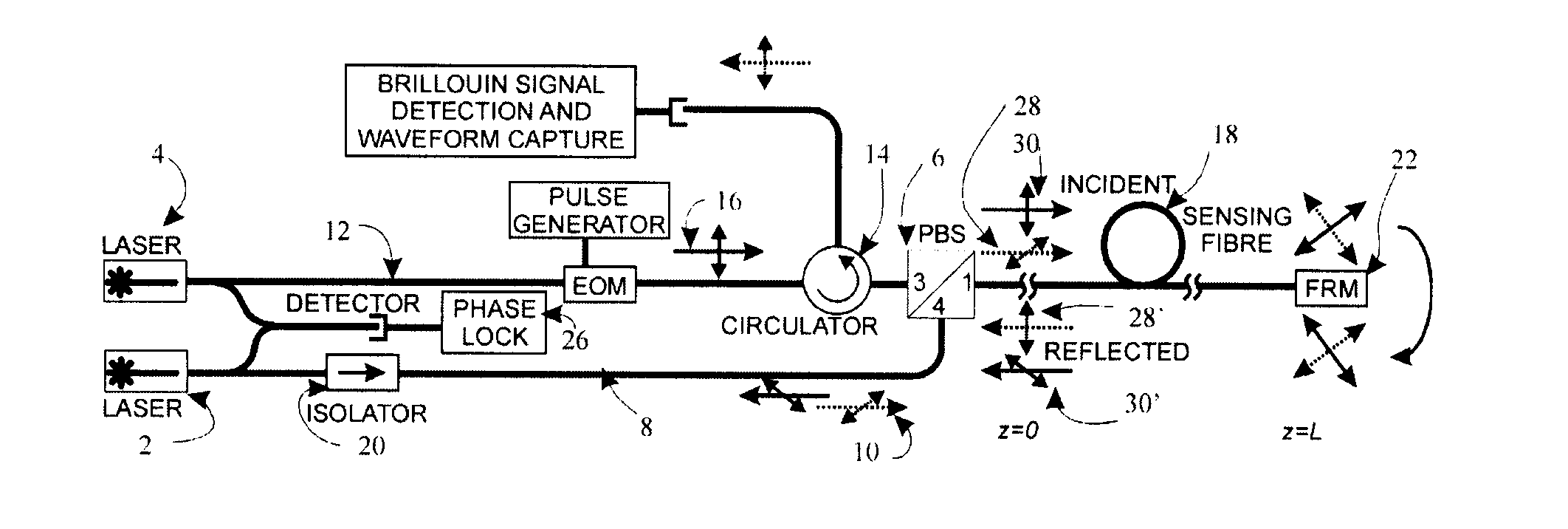
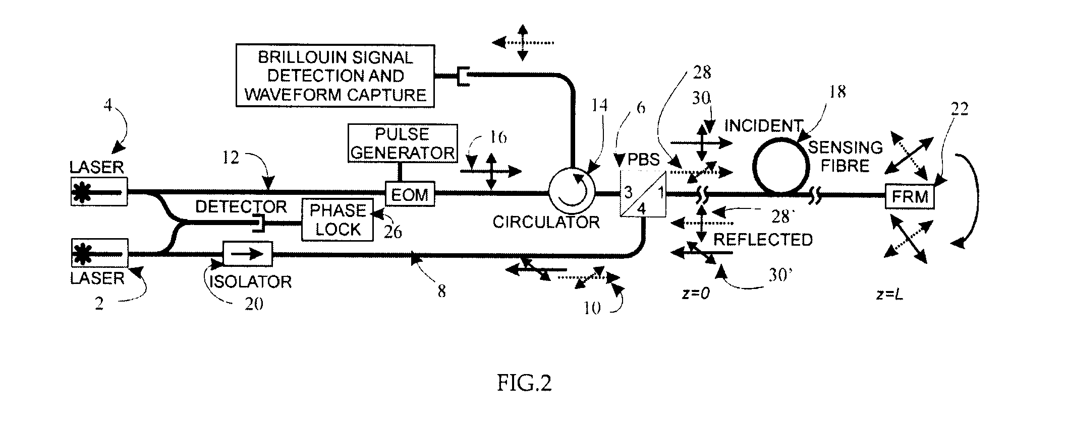
[0054]A time-domain signal produced by the BOTDA system of FIG. 2 is shown in FIG. 5. The test fibre consisted of a concatenation of alternating lengths of Corning SMF-28 and OFS Ultrawave SLA (the locations of the latter are indicated in FIG. 5), the two fibres having different Brillouin frequencies. In this sample waveform, the sensor is tuned to the Brillouin frequency of the Ultrawave SLA fibre. The location of the FRM is indicated at 24 in FIG. 5, and it will be observed that the signal is essentially a mirror image about this point. The signal strength is observed to be slightly less in the second half of the waveform due to the insertion loss of the FRM.

[0055]Data was collected, as in a standard BOTDA system, by sweeping through a range of Brillouin frequencies from 10.9 GHz to 11.1 GHz in steps of 2 MHz. The system used the dark pulse technique in a Brillouin loss configuration and had a spatial resolution of about 800 mm. At each point in the time domain, the spectral data ...


PUM

PropertyMeasurementUnit
Brillouin Opticalaaaaaaaaaa
phaseaaaaaaaaaa
temperatureaaaaaaaaaa

Abstract

A Brillouin analysis sensor system comprising: a Brillouin analysis sensor; a polarization beam splitter / combiner, operably connected to the Brillouin analysis sensor between the sensor and the sensing fibre, for receiving polarized lightwaves from the sensor, combining the lightwaves and launching combined lightwaves waves in the sensing fibre a first direction, and a phase conjugate mirror at a free end of the sensing fibre for receiving combined lightwaves from the polarization beam splitter / combiner, rotating the polarization of the combined lightwaves and launching the rotated combined lightwaves in the sensing fibre in an opposing direction to the first direction.

Description

FIELD[0001]The present invention relates to fibre optic distributed sensor systems and methods and, in particular, to systems and methods employing Brillouin analysis.BACKGROUND[0002]A Brillouin analysis sensor is a fibre optic distributed sensor that can measure changes in the local strain and / or temperature conditions of an optical sensing fibre through analysis of the Brillouin frequency of the sensing fibre at any point. The sensing fibre is usually attached to or embedded in a host material and is used to measure the strain and / or temperature conditions of the host. Both strain and temperature cause a shift in the Brillouin frequency. Position is determined by the round-trip transit time of the optical signal in the fibre. Reference herein to a Brillouin analysis sensor system shall mean a Brillouin analysis sensor plus an optical sensing fibre.[0003]A Brillouin analysis sensor system operates on the principle of Brillouin amplification. In a Brillouin amplifier, a signal (or S...

Claims


Application Information

Patent Timeline
Patent Type & Authority Applications(United States)
IPC IPC(8): G01J4/00G01K11/32G01B11/16
CPCG01K11/32G01K2011/322G01D5/35364G01B11/18G01L1/242G01K11/322
Inventor BROWN, ANTHONY
Owner DARKPULSE TECH INC
Why Eureka
Try Eureka