Easily solderable shield case for electromagnetic wave shielding

a shield case and electromagnetic wave technology, applied in the direction of shield case/cabinet/drawer details, magnetic/electric field screening, electrical equipment, etc., can solve the problems of reducing the quality of shield case, affecting the productivity and quality of metal shied cases, and compromising the reliability of reflow soldering through surface mount processes. to achieve the effect of ensuring the quality of shield cases

Inactive Publication Date: 2012-11-08
JOINSET
View PDF8 Cites 35 Cited by
  • Summary
  • Abstract
  • Description
  • Claims
  • Application Information

AI Technical Summary

Benefits of technology

[0036]In addition, since a protruded portion of the solder members are received by the solderable via holes or recesses formed in a ground pattern, moving and misaligning of the shield case are suppressed during reflow soldering, thereby ensuring quality of the shield case.
[0037]In addition, the solder members disposed on the flanges can be removed using heat after reflow soldering, thereby facilitating a reworking process.

Problems solved by technology

However, such metal shield cases are inappropriate for a surface mount process using vacuum pickup and a reflow soldering process using solder cream or flux, and thus, it is difficult to ensure the productivity and quality of the metal shied cases.
In this case, when the shield case is large, it may be difficult to maintain the lower end of the shield case in a horizontal position, which jeopardizes the reliability of reflow soldering through a surface mount process.
In addition, an airflow generated during reflow soldering may move a shield case, which also jeopardizes the reliability of reflow soldering.
In addition, since a shield case should be entirely plated with a soldering metal such as stanuum, for soldering of the lower end of the shield case, manufacturing costs thereof are increased.
In addition, after the lower end of a side wall of a shield case is entirely soldered, reworking of the shield case may be difficult.
However, a metal clip for fixing a shield case is lightweight and has a length greater than a width thereof, and thus, is susceptible to shaking and torsion during reflow soldering.
Thus, even when just one of metal clips is not in position, inserting of a shield case having predetermined dimensions may be difficult.
In addition, after soldering of metal clips, a shield case is manually fitted in the metal clips, which reduces productivity.
However, since the punctured material is thicker than a shield case formed from a metal foil, the punctured material is inappropriate to be used a small device such as a mobile device.
In addition, the treating of the punctured material with a metal is expensive.
Furthermore, it is difficult to install the punctured material on the solder spheres formed in advance on the printed circuit board.
Moreover, reworking of the punctured material is difficult, and the thermal conductivity thereof is low.

Method used


Image

  • Easily solderable shield case for electromagnetic wave shielding
  • Easily solderable shield case for electromagnetic wave shielding
  • Easily solderable shield case for electromagnetic wave shielding

Examples


Embodiment Construction

[0051]Embodiments of the present invention will be described below in more detail with reference to the accompanying drawings.

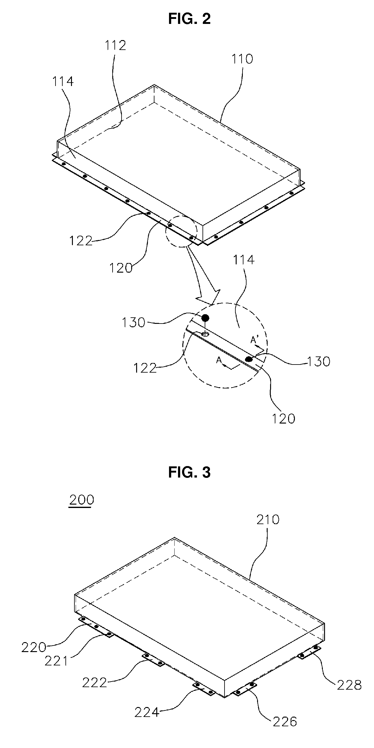
[0052]FIG. 2 is a perspective view illustrating a shield case 100 that is easily soldered and is used for electromagnetic wave shielding, according to an embodiment of the present invention.

[0053]The shield case 100 includes a main body 110, a plurality of flanges 120, a plurality of through holes 122, and a plurality of solder members 130 such as solder balls. The main body 110 is formed of an electrically conductive metal, and has a box shape with an opening 112 in a surface thereof (in a lower surface in the current embodiment). The flanges 120 extend outward or inward along edges of the opening 112, and are integrally formed with the main body 110 in one piece. The through holes 122 are arrayed along the flanges 120. The solder members 130 are placed in the through holes 122, and protrude in a thickness direction of the flanges 120.

[0054]The shield case 1...


PUM


Abstract

An easily soldered shield case for electromagnetic-wave shielding comprises: a metal main body in the shape of a box of which the bottom surface is open; a flange which is formed extending integrally outward or inward from the open edge of the main body; a plurality of through holes formed along the flange or a plurality of recesses formed along the rear surface of the flange; and a solder member which is stably placed on the through holes or the recesses and projects in the thickness direction of the flange, wherein the shield case is mounted on a printed circuit board and the solder member is electrically and mechanically joined to the printed circuit board by means of soldering.

Description

REFERENCE TO RELATED APPLICATIONS[0001]This is a continuation of pending International Patent Application PCT / KR2011 / 000624 filed on Jan. 28, 2011, which designates the United States and claims priority of Korean Patent Application No. 10-2010-0009977 filed on Feb. 3, 2010, and Korean Patent Application No. 10-2011-0008784 filed on Jan. 28, 2011, the entire contents of which are incorporated herein by reference.FIELD OF THE INVENTION[0002]The present invention relates to a shield case for electromagnetic wave shielding, and more particularly, to a shield case for electromagnetic wave shielding, which is soldered to a ground pattern of a printed circuit board. In addition, the present invention relates to a shield case for electromagnetic wave shielding, which is appropriate for a reflow soldering process and a surface mount process using vacuum pickup so as to improve productivity and reworking efficiency.BACKGROUND OF THE INVENTION[0003]In general, a high frequency electronic part ...

Claims


Application Information

Patent Timeline
Patent Type & Authority Applications(United States)
IPC IPC(8): H05K9/00
CPCH05K9/0032H05K9/0028H05K9/00H05K5/02
Inventor KIM, SUN-KI
Owner JOINSET
Why Eureka
Try Eureka