Preventing load dump overvoltages in synchronous rectifiers,

a synchronous rectifier and load dump technology, applied in the direction of electric generator control, safety/protection circuit, dynamo-electric converter control, etc., can solve the problems of sudden reduction, inability to compensate for sudden reduction, and inability to recreate properties to 100%, etc., to achieve low cost, simple activation, and low cost

Inactive Publication Date: 2012-11-08
ROBERT BOSCH GMBH
View PDF2 Cites 6 Cited by
  • Summary
  • Abstract
  • Description
  • Claims
  • Application Information

AI Technical Summary

Benefits of technology

[0015]In contrast to the previously mentioned related art, only a corresponding load dump recognition between the battery poles (B+ and B−) is necessary in the present invention due to the use of a time-controlled method in which the load dump does not have to be recognized in each individual phase. For the voltage analysis of each individual phase, a simple comparison is sufficient, for example. A determination of a load dump situation and a subsequent introduction of the measures according to the present invention are thus executable very easily and reliably. The actual energy-reducing measures within the load dump (i.e., within the time period during which an energy reduction is necessary) may be carried out as soon as a load dump situation has been recognized on the basis of pure time control with the aid of an instantaneous rotational speed, for example, which correlates with the time period of the phases of a generated three-phase current. An overvoltage recognition in each individual phase, as is necessary in the related art mentioned above, is not necessary, however. With regard to the electromagnetic compatibility, no disadvantages are to be expected since the activation frequency is reduced due to the proposed approach and is not increased as is the case in the related art.
[0018]Within the scope of the present invention, individual phases of the rectifier are thus temporarily short-circuited during a load dump. It is to be pointed out that no high-frequency clocking of the activation of the corresponding switching elements must be carried out for this purpose, but rather that the clocking pattern must be modified in such a way that individual switching elements remain switched on for a longer period of time (for example, by factor 3). In this way, the voltage supply by a corresponding generator rectifier continues to be ensured and a simple activation is possible with little effort. The power output of the generator is, however, considerably reduced since the arising power loss, which results in the particular “zenering” arm, is temporarily short-circuited. For this reason, a part of the additional power loss must be converted into heat in the (robust and thus suitable) generator, since fewer power losses may be converted into heat in the rectifier. The measures according to the present invention may be particularly advantageously used in five-phase systems; in principle, the method described above is also implementable in systems having a different number of phases, in particular systems having 3+n phases, with n=0, 1, 2 . . . .

Problems solved by technology

The load dump is always a critical case of error when designing an active rectifier.
It occurs if, in the case of an accordingly highly excited machine and an accordingly great portion of output current, the load at the generator is suddenly reduced (for example, by switching off the consumers), and this sudden reduction cannot be compensated for by capacitively acting elements in the vehicle electrical system (e.g., the battery).
In the MOSFETs presently available, these properties may, however, not be recreated to 100%.
However, such repeated clocking of a control signal within one half-wave (i.e., at a higher frequency than the applied alternating current phase in each case) has a series of disadvantages.
Apart from the formation of parasitic voltage peaks (having negative effects on the electromagnetic compatibility), high power losses are temporarily generated in the electrical switches, in particular during corresponding switching-off operations.
Even if the activation frequency of the limiting circuit is selected to be too low, there is the risk of parasitic voltage peaks being output into the sensitive vehicle electrical system.

Method used


Image

  • Preventing load dump overvoltages in synchronous rectifiers,
  • Preventing load dump overvoltages in synchronous rectifiers,
  • Preventing load dump overvoltages in synchronous rectifiers,

Examples


Embodiment Construction

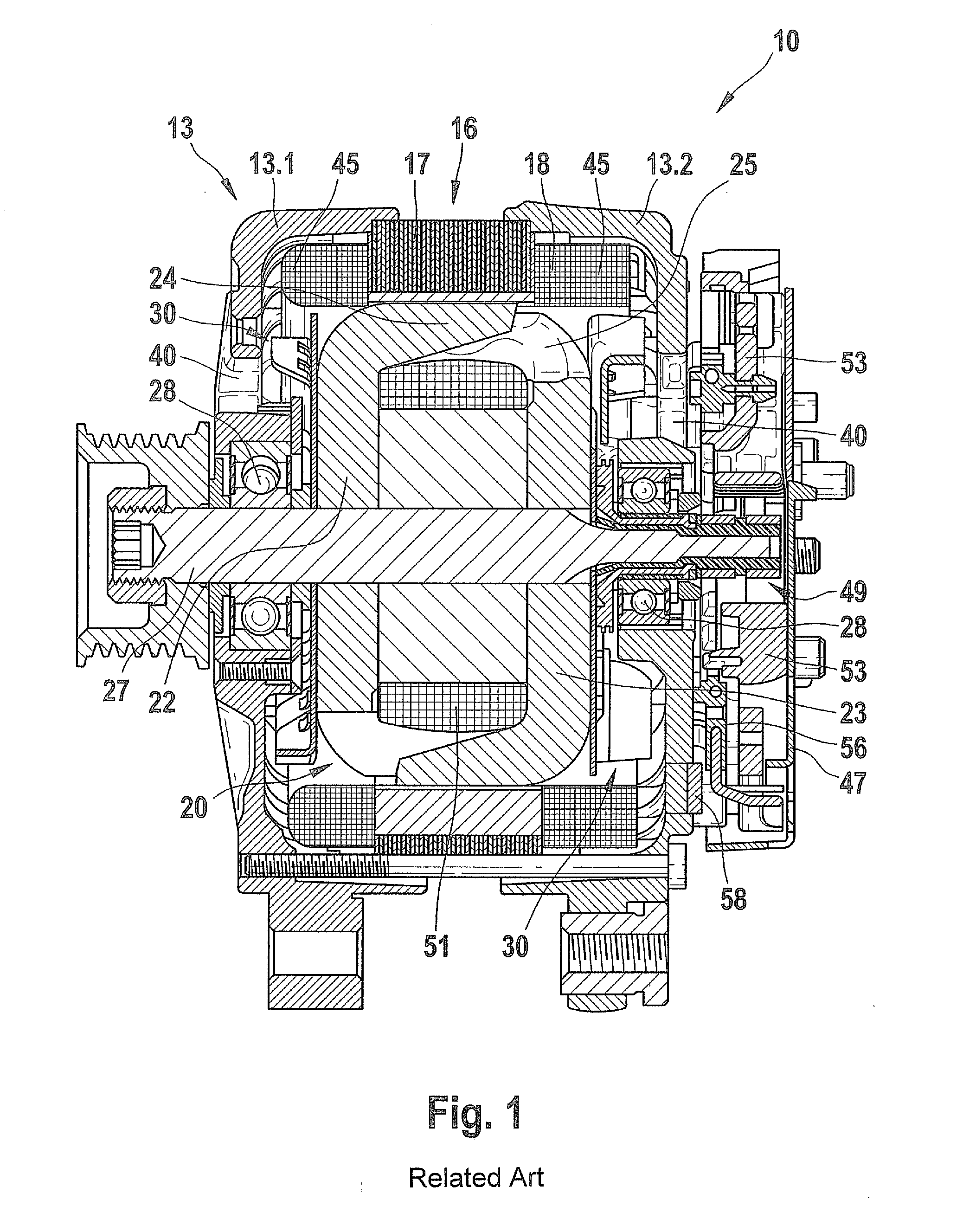
[0031]FIG. 1 shows a section through an alternating current generator 10 for motor vehicles according to the related art in which the method according to the present invention may be implemented.

[0032]The generator has a two-part housing 13 including a first end bracket 13.1 and a second end bracket 13.2. End bracket 13.1 and end bracket 13.2 accommodate a stator 16 having an annular lamination stack 17 into which a stator winding 18 is introduced. Stator 16 surrounds a rotor 20 with its radially internally oriented surface.

[0033]Rotor 20 has two claw-pole circuit boards 22 and 23 having claw-pole fingers 24 and 25 on their respective peripheries.

[0034]Both claw-pole circuit boards 22 and 23 are situated in such a way that their respective claw-pole fingers 24 and 25 alternate as north and south poles at the circumference of rotor 20.

[0035]Rotor 20 is rotatably mounted in particular end brackets 13.1 and 13.2 with the aid of a shaft 27 and each of rolling-contact bearings 28 located...


PUM


Abstract

In a method for reducing load dump overvoltages during operation of a synchronous rectifier for a polyphase alternating current having a number of inputs which correspond to the number of alternating current phases of the alternating current, and having at least two outputs for providing a direct current, an alternating current phase is connected to each of the inputs, and each of the inputs are electrically optionally connected via active switching elements to either the first or the second output in accordance with a control unit.

Description

BACKGROUND OF THE INVENTION[0001]1. Field of the Invention[0002]The present invention relates to a device and a method for preventing load dump overvoltages during operation of a synchronous rectifier for a polyphase alternating current.[0003]2. Description of Related Art[0004]It is known to use rectifiers for supplying direct current systems from three-phase current sources, e.g., the public three-phase system. The rectifiers are usually constructed as a bridge circuit, diodes being used as rectifier elements in the simplest case. These diodes do not require any additional control circuit since they automatically change to the conductive or blocking state at the right point in time, i.e., when the voltage threshold values are exceeded or are not reached.[0005]Six-pulse bridge rectifiers (in three-phase currents) are also used as rectifiers in three-phase current generators of motor vehicles (electric generators). Generators of this type have a pronounced inductive internal resistan...

Claims


Application Information

Patent Timeline
Patent Type & Authority Applications(United States)
IPC IPC(8): H02M7/06
CPCH02J7/1461H02P9/10H02P2101/45H02P2201/03H02P29/021H02P29/0241H02J7/14H02J7/0029
Inventor MAGINI, FABIOMEHRINGER, PAULSHENDI, ALEXANDERWINDMUELLER, ANDEASHERBIG, RALF
Owner ROBERT BOSCH GMBH
Why Eureka
Try Eureka