Methods and Systems for Variable Displacement Engine Control

a variable displacement, engine technology, applied in the direction of electric control, machines/engines, mechanical equipment, etc., can solve the problems of high in-cylinder pressure, degrading engine components, undesired detonation of internal combustion engines, etc., to reduce the average noise level of knock sensor, detect more reliably, and increase threshold

Active Publication Date: 2012-11-15
FORD GLOBAL TECH LLC
View PDF11 Cites 109 Cited by
  • Summary
  • Abstract
  • Description
  • Claims
  • Application Information

AI Technical Summary

Benefits of technology

[0005]Thus in one example, the above issue may be at least partly addressed by a method of operating a boosted engine with selectively deactivatable cylinders. In one example embodiment, the method comprises adjusting a window and a threshold for pre-ignition detection based on a number of deactivated cylinders. The method may further comprise, adjusting a window and a threshold for knock detection based on the number of deactivated cylinders. In this way, by adjusting both the threshold and the window for each of knock and pre-ignition based on the deactivation, pre-ignition may be detected more reliably.
[0006]In one example, an engine may include a first group of cylinders with a first downstream exhaust catalyst, and a second group of cylinders with a second downstream exhaust catalyst. An engine control system may select a cylinder group for deactivation based on the regeneration state and temperature of the catalysts, and further based on a deactivation order. Then based on the number of deactivated cylinders in the selected cylinder group, the control system may adjust the window and threshold for each of knock detection a

Problems solved by technology

Internal combustion engines may be susceptible to undesired detonation, such as engine knock or pre-ignition, under various conditions.
Undesired detonation may cause high in-cylinder pressures and temperatures that can degrade engine components as well as decrease engine efficiency.
However, the inventors herein have identified potential issues with such an approach.
For example, even with the mode-adjusted knock thresholds, cylinder pre-ignition may not be reliably detected or diff

Method used


Image

  • Methods and Systems for Variable Displacement Engine Control
  • Methods and Systems for Variable Displacement Engine Control
  • Methods and Systems for Variable Displacement Engine Control

Examples


Embodiment Construction

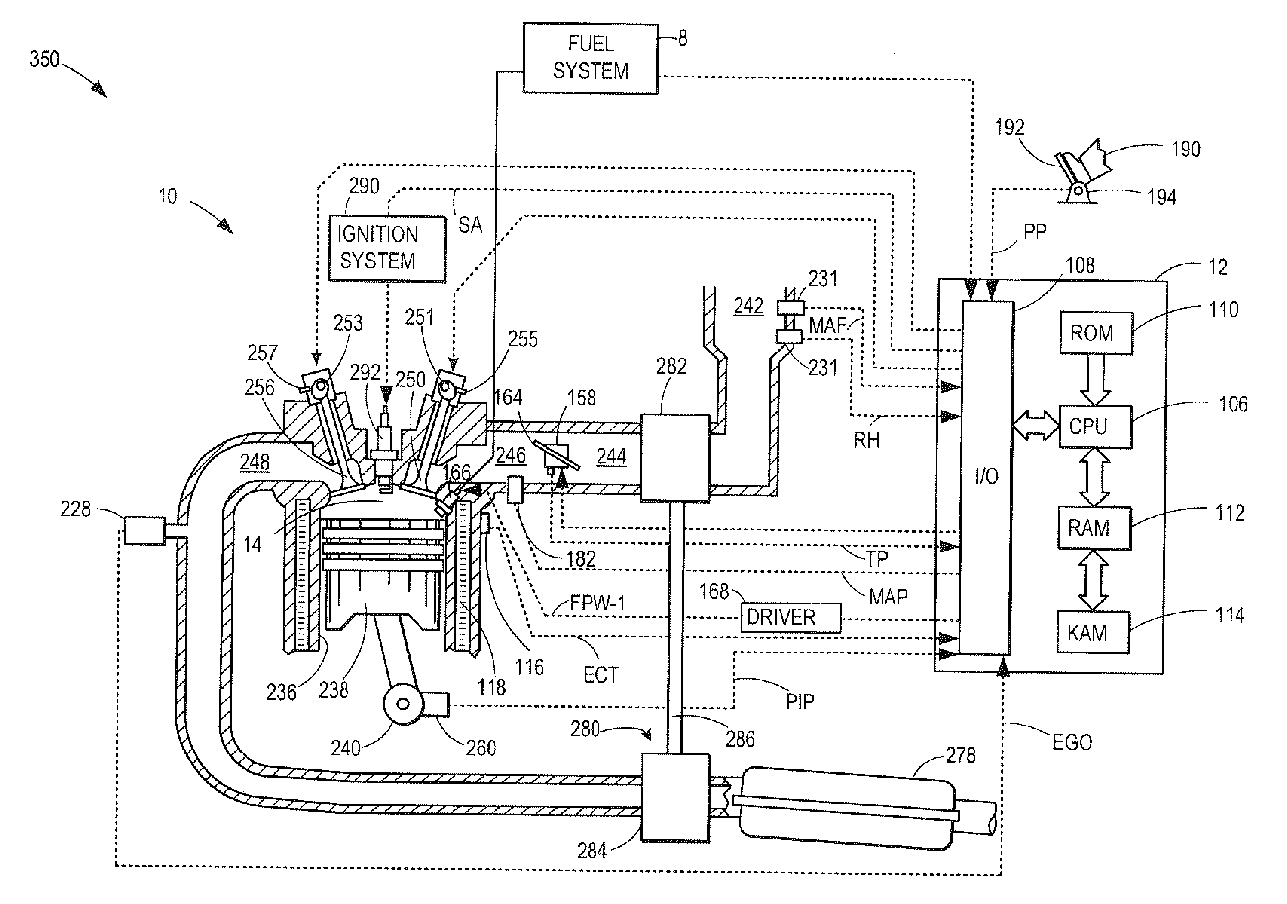
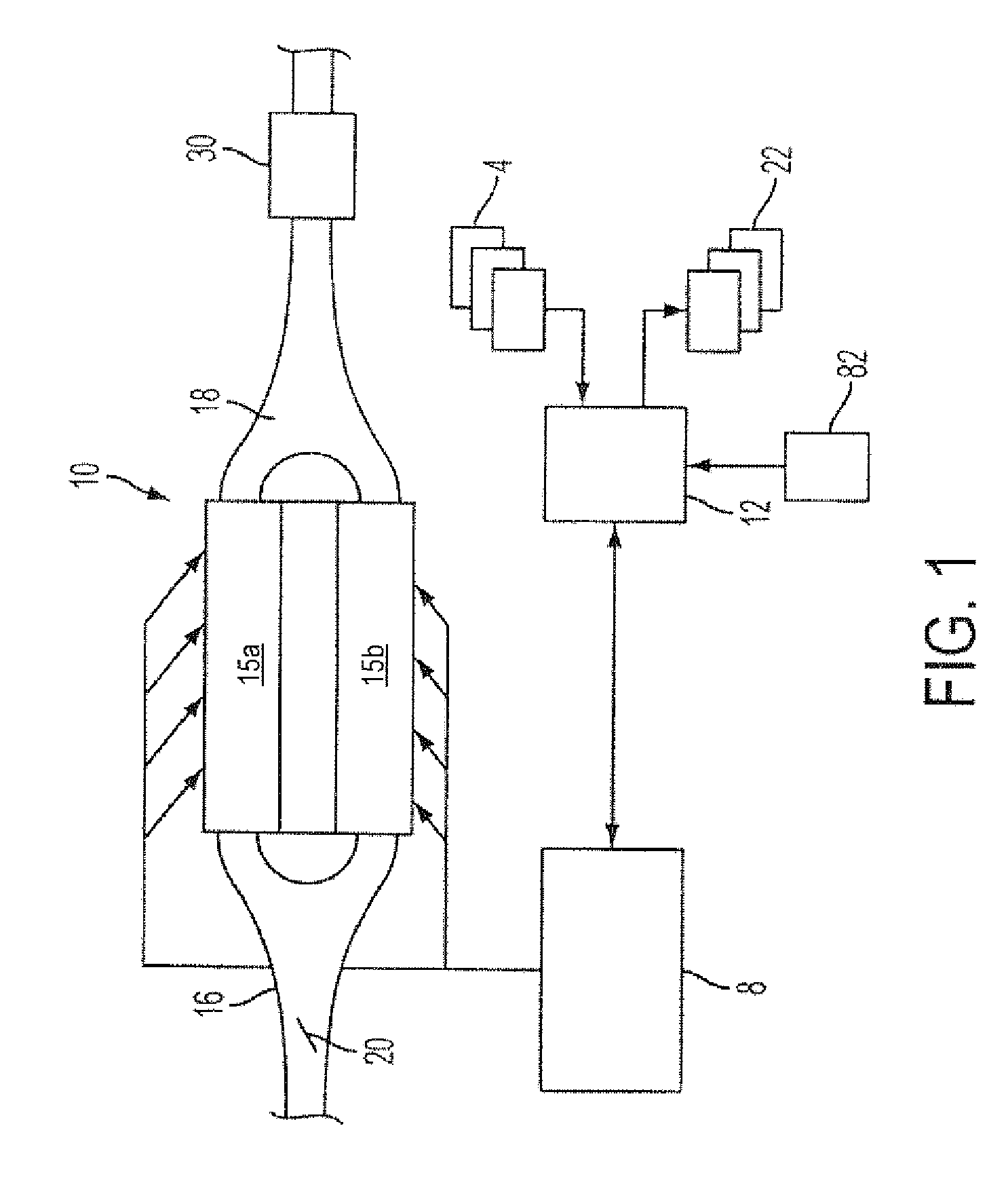
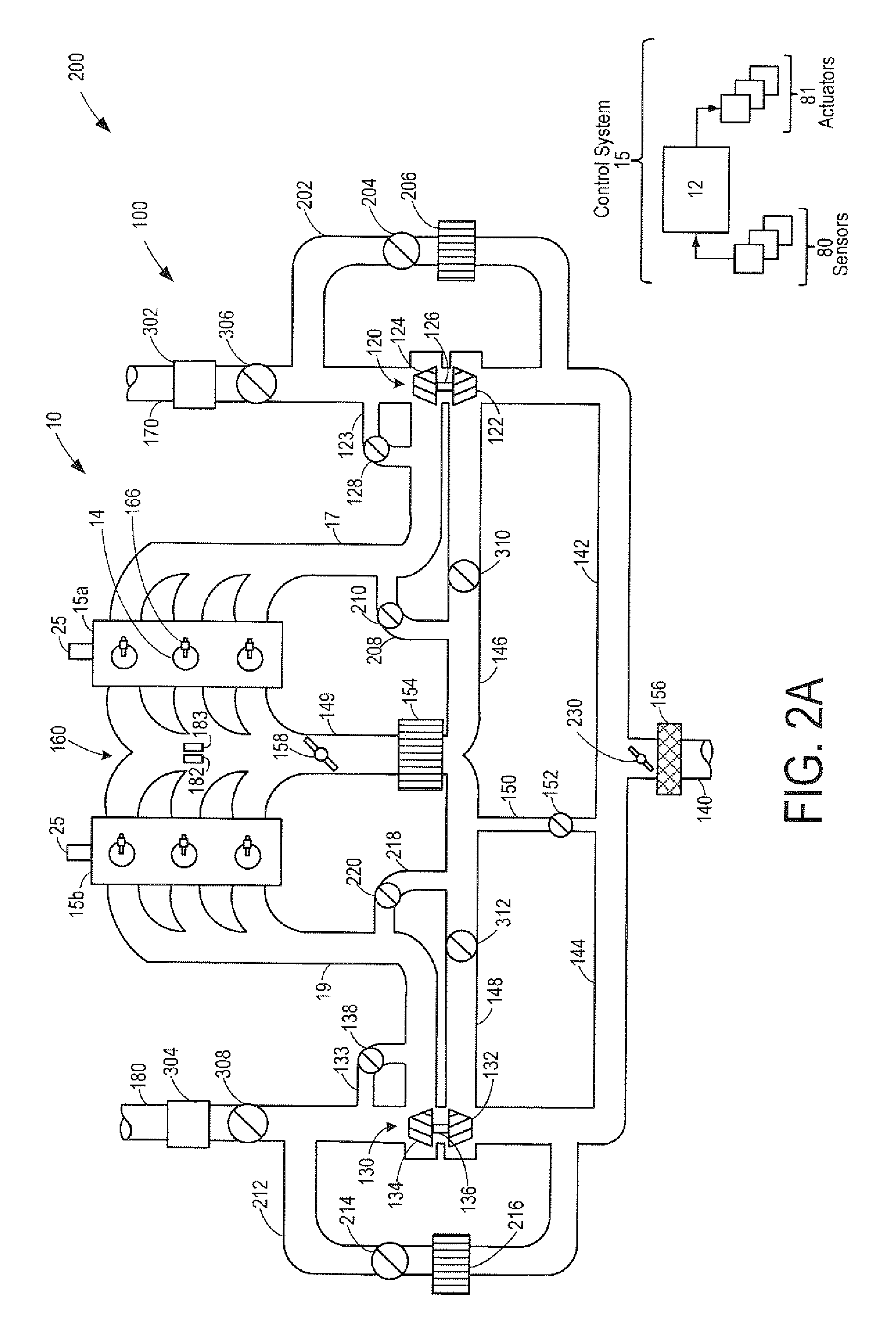
[0016]The following description relates to systems and methods for adjusting cylinder operation in a boosted engine system (such as the VDE engine system of FIGS. 1-3). The engine system may switch between operation with all cylinders firing or fewer cylinders firing by selectively deactivating one or more cylinder fuel injectors. An engine controller may select a group of cylinders for deactivation based on a regeneration state of a downstream catalyst (FIGS. 4-5). Based on the selection, the position of one or more valves and throttles may be adjusted to maintain catalyst temperature, reduce back-flow through the disabled group of cylinders, improve boost operations, and coordinate EGR operations with VDE operations (FIGS. 6-7). The engine control system may also adjust each of a window and a threshold for knock and pre-ignition detection based on the deactivation (FIG. 8) to improve detection and mitigation of abnormal cylinder combustion events. In this way, by adjusting various...


PUM


Abstract

Methods and systems are provided for selecting a group of cylinders for selective deactivation, in a variable displacement engine system, based at least on a regeneration state of an exhaust catalyst. The position of one or more valves and throttles may be adjusted based on the selective deactivation to reduce back-flow through the disabled cylinders while also maintaining conditions of a downstream exhaust catalyst. Pre-ignition and knock detection windows and thresholds may also be adjusted based on the deactivation to improve the efficiency of knock and pre-ignition detection.

Description

FIELD[0001]The present application relates to methods and systems for controlling a variable displacement engine (VDE).BACKGROUND AND SUMMARY[0002]Internal combustion engines may be susceptible to undesired detonation, such as engine knock or pre-ignition, under various conditions. Undesired detonation may cause high in-cylinder pressures and temperatures that can degrade engine components as well as decrease engine efficiency. Various approaches have been developed for identifying and distinguishing pre-ignition and knock, including using acoustic sensors or accelerometers placed on an engine, as well as internal cylinder pressure sensors and ionization sensors. For example, knock and pre-ignition may be identified and distinguished based on differences in timing and intensity when compared to threshold values. Likewise, following detection, distinct steps may be taken for mitigating knock and pre-ignition.[0003]One example approach for addressing knock in displacement on demand (D...

Claims


Application Information

Patent Timeline
IPC IPC(8): F02B33/44F01N3/18F02B33/00
CPCF02D41/0087F02D2200/0802F02D41/027F01N13/011F02P5/152F01N2430/02F01N13/107Y02T10/46F02D35/027Y02T10/40F02B37/00
Inventor KERNS, JAMES MICHAELUHRICH, MICHAEL JAMESSMITH, STEPHEN B.BANKER, ADAM NATHAN
Owner FORD GLOBAL TECH LLC
Why Eureka
Try Eureka